


IN-V300-07
1.0 General Description
The V300 Stroke Rate Controller provides precision
flow control for FMI variable speed "V" Series pumps.
The V300 accomplishes this by varying the pump
stroke rate from 5% to 100% of the drive’s rated speed
range of 90 to 1800 Strokes per Minute (SPM). The
complete pump system consists of the V300 Controller
and a variable speed "V" Series Pump. The V300 and
pump are connected via a single cable (standard
length is 4 meters while optional extension cables up to
20 meters are readily available).
The pump is comprised of a 90 volt DC pump drive
module (PDM) with integrally mounted pump head
module (PHM), and is available in two configurations,
QV and RHV, to accommodate FMI's full range of
pump head sizes.
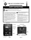
1.1 Features (See Figures 1 & 2)
Convenient front panel membrane switches for
Run, Stop, Increase Flow & Decrease Flow.
3 1/2 Digit LCD displays percent of Flow/Speed.
Selectable Manual or Analog flow rate control.
Manual setting of flow rate with 0.1% adjustability
Analog Input selectable 4-20 mA, 0-5 VDC, and
0-10 VDC input for communication with process
instrumentation.
Start, Stop, and Reverse Flow while maintaining
flow settings.
Current fold back eliminates stalled motor/
electronics damage.
Universal Power accepts 100-240 VAC 50/60 Hz
Quick connections for power, analog input, and
pump modules.
Rugged, Anodized Aluminum Enclosure designed
for bench-top or wall mounting.
2.0 Specifications
( See Fig. 3 Page 5)
2.1 Power In
Supply Voltage: 100-240VAC +/- 10%, 50/60 Hz.
Main Supply Current: 0.5 Amp
Fuses: T250V-1A (time lag), 5x20mm, 2 required
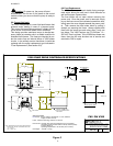
2.2 Physical
Dimensions: 7" H x 6 1/8" W x 4 3/4" D (180 x 158 x
120 mm) Weight: 3.8 lbs. (1.72kgs)
2.3 Environment
Humidity: 80% max for temperatures up to 31°C,
decreasing linearly to 50% relative humidity at 40°C.
Pollution degree, 2
Operating temperatures range from 5ºC to 40ºC (41ºF
to 104ºF)
3.0 Installation & Setup
3.1 Installation:
The V300 modules are designed to operate on a Table-
top or as a Wall-mount (secured to a wall panel - see
Figure 4 for template)
3.1.1 Table-top:
The system is configured for table top installation ini-
tially with rubber grommets slid into the mounting slots.
Before moving on to configuring the control module,
make sure that these rubber grommets are in place.
There are no further installation steps for table top use.
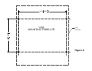
3.1.2 Wall-Mounting:
For wall mounting, it is necessary to remove the four
rubber grommets from the control module before
attempting to mount. Each unit must be mounted in the
correct orientation; with the labels facing right side up,
the control module will have the cables at the bottom,
the pump module will have the pump mounted to the
bottom as well. Wall mounting may require an appro-
priate mounting board of at least 1/2”(12mm) thickness
to straddle the studs of a typical plasterboard wall. See
Figure 4
Caution:
Do not mount V300 Controller or Pump
Modules directly to plaster board.
3.2 Setup:
The configuration is set by selecting one of four inter-
face modes accomplished with a 'set and forget' screw-
driver slotted mode switch located on the front panel.
The controller also incorporates a screwdriver slotted
pump reversing switch on the front panel to facilitate
special maintenance requirements. In all cases, the
stroke rate is limited to a minimum of 5.0% and a max-
imum of 100.0% providing a stroke rate of 90 (5.0%)
to 1800 (100.0%) strokes per minute.
The reversing switch is marked as "REV", "OFF", and
"FWD". It must be set to "FWD" for normal operation.
(See Figure 1)
Note: If the reversing switch is changed while the
motor is running, the control module will shut down the
pump and wait until the user presses "RUN". If the
switch is left in the "OFF" position, the display will indi-
cate a steady "OFF" condition.
The "RUN" button will start the pump drive module.
The display will indicate the current stroke rate. The
"STOP" button will immediately stop the pump and the
display will alternate between "OFF" and the current
stroke rate. The pump will remain "OFF" until the user
presses "RUN".
Caution:
Do not attempt to apply power to the control
unit until it is configured to one of the following modes.
3.2.1 Manual Mode
Use this mode if you want to control the stroke rate
manually. This mode allows you to select a stroke rate
by pressing the up and down arrows located next to the
2
!
!