


15
107105
OWNER’S MANUAL
INSTALLATION
Continued
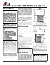
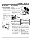
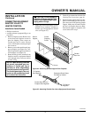
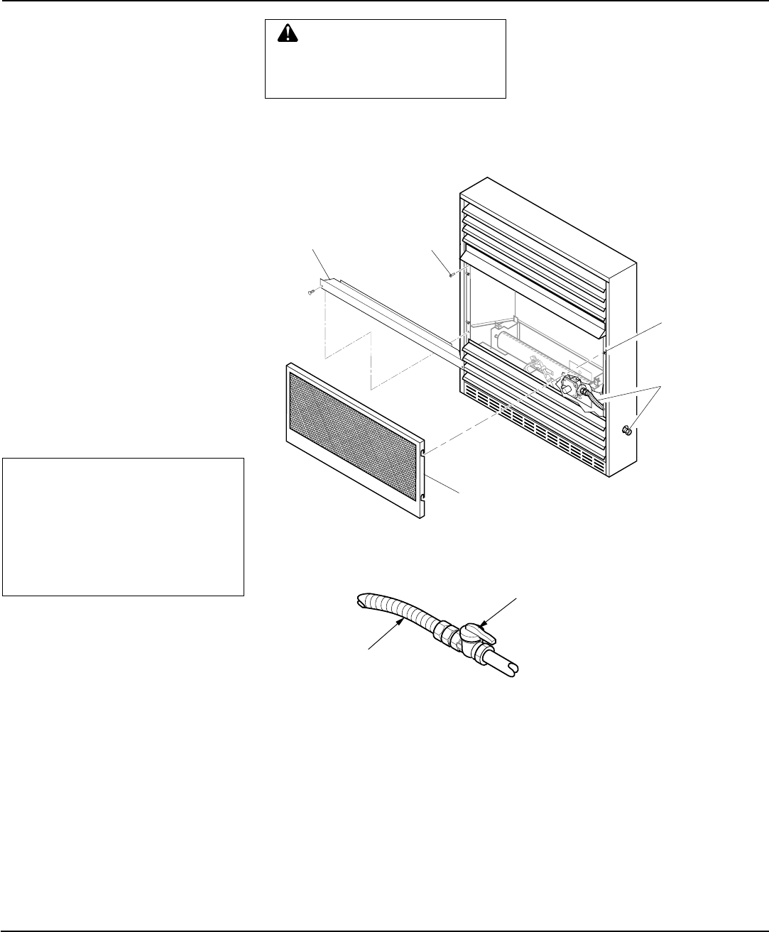
Figure 24 - Removing Branch Support From Fireplace
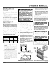
CONNECTING EQUIPMENT
SHUTOFF VALVE TO
HEATER CONTROL
Installation Items Needed
• Phillips screwdriver
• sealant (resistant to propane/LP gas, not
provided)
1. Remove fireplace screen. Remove two
screws that hold fireplace screen in
place for shipping. These screws are
located near top of screen. Discard
screws. Lift fireplace screen up and pull
out to remove.
2. Remove screws that attach branch sup-
port to fireplace (see Figure 24). Care-
fully lift up branch support and remove
from fireplace (see Figure 24).
3. Route flexible gas line, included, from
fireplace control to equipment shutoff
valve through side or rear access holes
in outer casing.
NOTICE: Most building codes do
not permit concealed gas con-
nections. A flexible gas line is
provided to allow accessibility
from the fireplace (see Figure 25).
The flexible gas supply line con-
nection to the equipment shutoff
valve should be accessible.
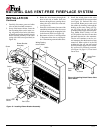
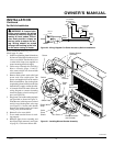
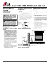
Figure 25 - Attaching Flexible Gas Line to Equipment Shutoff Valve
4. Apply pipe joint sealant lightly to male
threads of gas connector attached to
flexible gas line/equipment shutoff
valve (see Figure 25).
Branch
Support
Screen
Screen
Shipping
Screw
Shoulder
Screw
Flexible
Gas Line
Continued
CAUTION: Avoid damage to
regulator. Hold gas regulator with
wrench when connecting it to gas
piping and/or fittings.
➞
➞
Flexible Gas Line from
Fireplace Gas Regulator
To Fireplace
Gas Regulator
Equipment Shutoff Valve
Provided by Installer
To External
Regulator
5. Check all gas connections for leaks. See
Checking Gas Connections, page 16.
6. Replace branch support back into fire-
place. Feed flexible gas line into fire-
place base area while replacing branch
support. Make sure the entire flexible
gas line is in fireplace base area. Reat-
tach branch support to fireplace with
screws removed in step 2.