


www.fmiproducts.com
124971-01C26
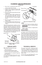
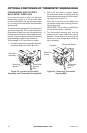
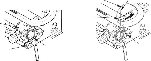
OPTIONAL POSITIONING OF THERMOSTAT SENSING BULB
Thermostat
Sensing
Bulb
Gas Valve
Assembly
Mounting
Bracket
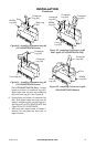
Figure 30 - Location of Gas Valve
Assembly and Thermostat Sensing Bulb
Figure 31 - Removing Thermostat
Sensing Bulb
Thermostat Screw
Retaining
Clamp
Thermostat
Sensing
Bulb
Capillary
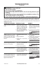
FOR MASONRY AND FACTORY-
BUILT METAL FIREPLACE
If your log set cycles to pilot, but the room
temperature drops to a lower than ideal
comfort level before the log set comes back
on, you may want to reposition the thermostat
sensing bulb.
The thermostat sensing bulb is located on the
gas valve assembly. This location allows the
thermostat to keep the room temperature at
an ideal comfort level for most replace appli-
cations. If positioning the thermostat sensing
bulb elsewhere, follow these directions.
Tools needed: 5/16" hex driver or socket
1. Locate the gas valve assembly and ther-
mostat sensing bulb (see Figure 30).
2. With 5/16” hex driver or socket, loosen
the thermostat screw. Carefully slide the
thermostat sensing bulb out of the retain-
ing clamp (see Figure 31).
Note: Do not remove screw. Make sure
you tighten screw after removing thermo-
stat sensing bulb.
IMPORTANT: Do not force or bend ther-
mostat sensing bulb or capillary.
3. The thermostat sensing bulb may be
located to the lower right front side of
replace. Place bulb in an area that will
be close to room temperature when log
set is operating