


www.fmiproducts.com
124971-01C14
CAUTION: Avoid damage to
regulator. Hold gas regulator
with wrench when connecting it
to gas piping and/or ttings.
INSTALLATION
Continued
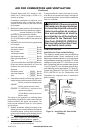
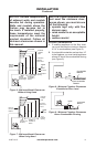
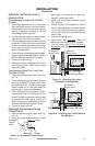
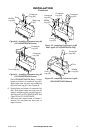
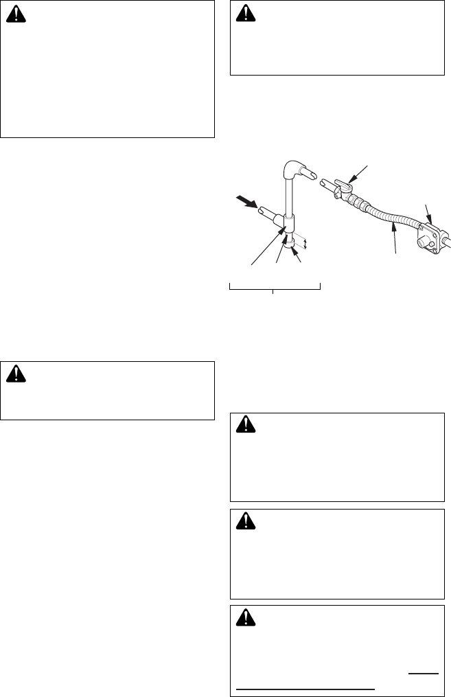
Figure 13 - Gas Connection
* Purchase the optional equipment shutoff
valve from your dealer.
** Minimum inlet pressure for purpose of input
adjustment.
3" Minimum
Sediment Trap
Gas
Regulator
Equipment Shutoff
Valve With 1/8" NPT
Tap*
Approved Flexible
Gas Hose (if allowed
by local codes)
Tee Pipe Cap
Joint Nipple
PROPANE/LP
From External Regulator
(11" W.C.** to 14" W.C.
Pressure)
NATURAL
From Gas Meter
(5" W.C.** to
10.5" W.C.
Pressure)
CHECKING GAS CONNECTIONS
WARNING: Test all gas pip-
ing and connections, internal
and external to unit, for leaks
after installing or servicing. Cor-
rect all leaks at once.
WARNING: Never use an open
ame to check for a leak. Apply a
noncorrosive leak detection uid
to all joints. Bubbles forming show
a leak. Correct all leaks at once.
CAUTION: Make sure exter-
nal regulator has been installed
between propane/LP supply and
heater. See guidelines under Con-
necting to Gas Supply, page 13.
CAUTION: Use only new, black
iron or steel pipe. Internally-tinned
copper tubing may be used in
certain areas. Check your local
codes. Use pipe of 1/2" diameter
or greater to allow proper gas vol-
ume to heater. If pipe is too small,
undue loss of volume will occur.
Installation must include an equipment shutoff
valve, union and plugged 1/8" NPT tap. Locate
NPT tap within reach for test gauge hook up.
NPT tap must be upstream from heater (see
Figure 13).
IMPORTANT: Install equipment valve in an
accessible location. The equipment shutoff
valve is for turning on or shutting off the gas
to the appliance.
Check your building codes for any special
requirements for locating equipment shutoff
valve to replaces.
Apply pipe joint sealant lightly to male NPT
threads. This will prevent excess sealant from
going into pipe. Excess sealant in pipe could
result in clogged heater valves.
WARNING: Use pipe joint
sealant that is resistant to liquid
petroleum (LP) gas.
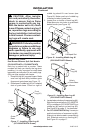
We recommend that you install a sediment
trap in supply line as shown in Figure 14.
Locate sediment trap where it is within reach
for cleaning. Install in piping system between
fuel supply and heater. Locate sediment trap
where trapped matter is not likely to freeze.
A sediment trap traps moisture and contami-
nants. This keeps them from going into heater
controls. If sediment trap is not installed or is
installed wrong, heater may not run properly.