


www.fmiproducts.com
122280-01E 11
PREINSTALLATION PREPARATION
Continued
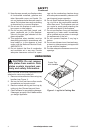
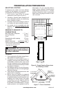
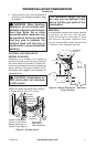
6. Using screws or nails, secure replace to
framing through anges located on sides
of replace.
-
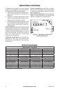
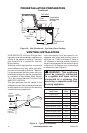
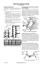
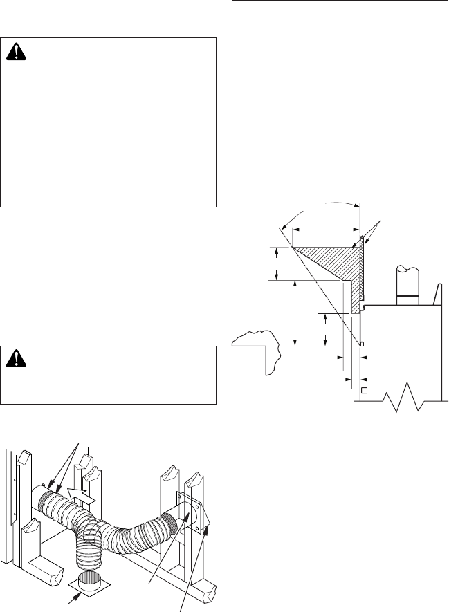
OPTIONAL OUTSIDE AIR KIT
(MODEL AK4/AK4F)
Installation of an outside air kit should be
performed during rough framing of replace
due to the nature of it's location. Outside com-
bustion air is accessed through a vented crawl
space (AK4F) or through a sidewall (AK4).
See Figure 39 on page 32 for instruction of
operating air kit.
in attic space.
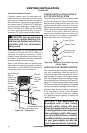
3" (7.6 cm)
1
1
/
2
"
(3.8 cm) Max.
8"
6" (15.2 cm)
14"
12"
(22.9 cm)
Combustible
Materials
30°
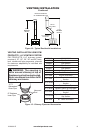
Figure 9 - Mantel Clearances - Side View
(Cross Section)
Figure 8 - Outside Air Kit
Secure to Collars with Metal Tape, Screws
or Straps (Min. of 1/4" x 20" in size)
Air Inlet
Location
Must Allow
For Bushes
or Snow
Vent Hood
Required for
Wall Installation
Air Inlet
Eyebrow
Vented Crawl Space
(Check Local Codes
Before Installing in a
Vented Crawl Space)
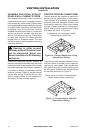
MANTELS
A combustible mantle shelf maybe installed
a maximum 12" (22.9 cm) from the wall.
Figure 9 and Figure 10 on page 12 show
the minimum allowable distances from
various combustible mantle components
in relation to the fireplace opening.