


www.fmiproducts.com
123492-01E 9
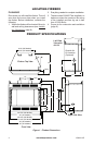
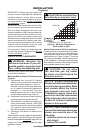
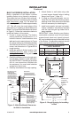
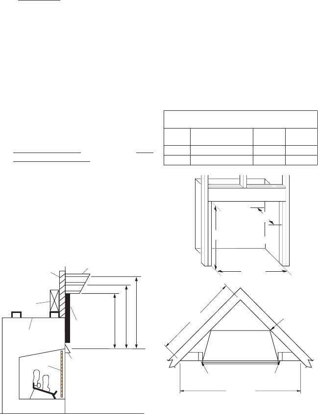
Maintain 3/4"
Clearance
at Sides and
Back of
Fireplace
66
7
/
8
"
72
7
/
8
"
47
3
/
8
"
52
1
/
2
"
3/4" Clearance Not
Required at Nailing Flanges
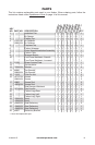
INSTALLATION
Continued
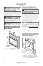
BUILT-IN FIREBOX INSTALLATION
Built-in installation of this rebox involves
installing rebox into a framed-in enclosure.
This makes the front of rebox ush with wall.
Optional brass trim accessories are available
(see Accessories, page 14). The brass trim
will extend past sides of rebox approximately
1/2". This will cover the rough edges of the
wall opening. If installing a mantel above the
rebox, you must follow the clearances shown
in Figure 5. Follow the instructions below to
install the rebox in this manner.
1. Frame in rough opening. The firebox
framing should be constructed of 2 x 4
lumber or heavier. Use dimensions in the
table and rough opening layout in Figure
6a. Adjust framing so that rebox ushes
with nished wall surface. If installing in a
corner, use dimensions in Figures 6b for
rough opening.
2. Install gas piping to rebox location. See
Installing Gas Line, page 10 and Con-
necting to Gas Supply in log set owner’s
manual.
3. Carefully set rebox in front of rough open-
ing with back of rebox inside wall open-
ing. IMPORTANT: If installing a perimeter
trim kit, see instructions included with
trim accessory. You must install shoulder
screws from trim kit now.
4.
Carefully insert rebox into rough opening.
5. Attach rebox to wall studs using nails
or wood screws through holes in nailing
ange (see Figure 7, page 10).
6. If using an optional perimeter trim kit,
install the trim after nal nishing and/or
painting of wall. See instructions included
with trim accessory for attaching trim.
7. Install and properly test gas log heater.
Follow installation instructions included
with the vent-free gas log heater that is
being installed.
IMPORTANT: When nishing your rebox,
combustible materials such as wall board,
gypsum board, sheet rock, drywall, plywood,
etc. may be butted up next to the sides and top
of the rebox. Combustible materials should
never overlap the rebox front facing.
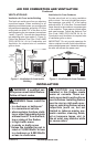
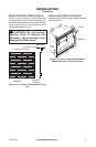
Figure 5 - Minimum Mantel Clearances
for Built-In Installation
Supplied
Firebox Hood
Must Be Used
at All Times
Wire-mesh
Screen
Firebox
Noncombustible
Material May
Project Off this
Surface above
the Firebox Hood
Mantel Shelf
Note: Any portion of the
mantel shelf must NOT
extend beyond this profile.
12" 16" 20"
1
1
/
2
"
6
3
/
4
"
12"
Note: All vertical
measurements are
from top of fireplace
hood opening to
bottom of mantel shelf.
These minimum
clearances replace any
other recommended
clearances supplied
with your ANSI Z21.11.2
approved gas logs.
Wall board or facing
material (above
firebox) may be of
combustible material,
including decorative
mantel ornaments or
other similar projec-
tions off of the facing
material.
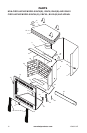
Framing
Material
Built-in Installation
Model
Front Width
(Inside to Inside) Height
Depth
(Min.)
36" 38
1
/
4
" 37
5
/
8
" 22"
42" 44
1
/
4
" 37
5
/
8
" 22"
Figure 6 - Rough Opening for Installing
in Wall
Depth
(Minimum)
Width
(Inside to Inside)
Height
Figure
6a
Figure
6b