


www.fmiproducts.com
115386-01D6
FIREPLACE INSTALLATION
Continued
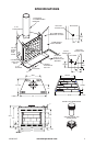
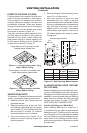
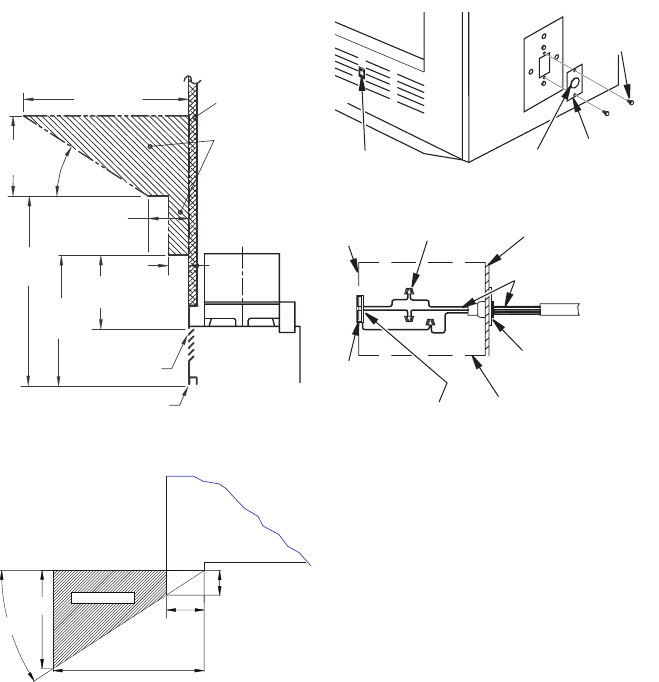
Figure 4 - Mantel Clearances to
Combustible Material
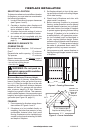
Electrical
Bushing
Electrical
Cover
Plate
Rocker
Switch
Figure 6 - Fan Switch-Electrical Bushing
Electrical
Housing
Wire Nut (3x)
(Not Supplied)
Outer Wrapper
of Fireplace
Electrical Cover
Plate and
Electrical Bushing
Fireplace Chassis
Ground
To Power
Source
Receptacle
(Supplied)
Power Source Wiring
(Not Supplied)
Prewired Receptacle
and Ground
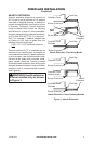
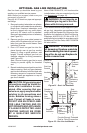
MANTELS
A mantel may be installed if desired (see
Figure 4). Woodwork such as wood trims,
mantels or any other combustible material
projecting from front face must not be placed
within 12" of replace opening (and within 9"
of top louver opening). Combustible materi-
als above 12" and projecting more than 1
1
/
2
"
from replace must not be placed less than
12" from top opening of replace (NFPA STD
211, Sec. 7-3.3.3).
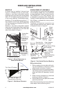
Mantels or any other combustible material
may come up to side edge of black metal face
of replace if projection from front face falls
within limits shown in Figure 5.
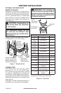
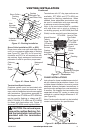
FAN/BLOWER KIT ASSEMBLY
Fan or blower kit is optional with this replace
(for circulating models only). Use of blowers
or fans other than those manufactured by
FMI PRODUCTS, LLC voids warranty. Fan
is operated by pressing rocker switch (see
Figure 6) in lower right hand corner of replace
face. Blower is operated by turning control
knob (not shown).
Fan/blower kit electrical connections are
made through electrical cover plate on side
of replace a shown in Figure 6.
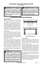
FIREBOX
SAFE ZONE
Figure 5 - Side Mantel Clearance
Top View of Fireplace
Min. 12" from
Perpendicular Side Wall
1"
0.625" Max.
33°
8"
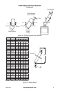
Wiring Instructions
1. Remove electrical cover plate with bush-
ing from replace by removing 2 sheet
metal screws as shown in Figure 6.
2. Slide power source wiring through electri-
cal bushing opening and electrical cover
plate and make all necessary connec-
tions.
3. Slide all wiring connections in electrical
housing as shown in Figure 6.
4. Secure electrical cover plate with screws
previously removed.
Note: Electrical housing and cover plate have
sharp edges. Wear protective gloves.
Sheet
Metal
Screws
12
1
/
4
" Ref.
1
1
/
2
"
Max.
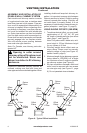
Upper Section
of Circulating
Fireplace
6"
Ref.
9"
Min.
33°
3" Nom.
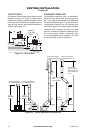
*Note: Drawing
Not To Scale
Safe Zone For
Projection of
Combustible
Materials
Combustible
Material
15"
Min.
12"
Min.
Fireplace Opening
Top of
Louvered
Opening