


80K-15
Electronic Air Cleaner Probe
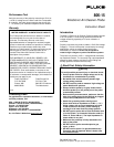
Symbols
T
Double insulated.
W
Refer to explanation in this instruction sheet.
X
Lethal voltages may be present.
Complies with relevant Canadian Standards
Association directives.
Earth ground
Using the Probe
87
TRUE RMS MULTIMETER
MIN MAX RANGE HOLD
H
HzREL
mA
A
V
V
OFF
!
!
A
COM
V
mAµA
1000V MAX
400mA MAX
FUSED
10A MAX
FUSED
PEAK MIN MAX
41/2 DIGITS
1 Second
µA
CAT II
III
mV
DC
5
3
4
1
2
EAOO1F.EPD
A Probe tip
B Probe body
C Plug
D GND tab
E Grounding lead clip
F Multimeter or voltmeter
Figure 1. 80K-15 Electronic Air Cleaner Probe
The 80K-15 (Figure 1) is designed to work with a meter that
has an input impedance of 10 MΩ ( ± 1% ). A meter with an
input impedance less than 10 MΩ can produce readings
lower than the voltage present. This can pose a serious
hazard when a dangerous voltage is present.
The 80K-15 represents a 1000 MΩ load to the circuit being
measured, or 1 µA per 1 kV. Table 1 shows the circuit
loading and input/output characteristics of the probe over its
measurement range.
Taking care to follow the safety practices under “WRead
First: Safety Information,” use the probe as follows:
1. Turn on a compatible voltmeter or multimeter and
select the voltage measurement function.
2. Select an appropriate voltage range (i.e., 1 volt reading
per 1000 volt input. See Table 1).
3. Connect the probe’s output leads to the voltmeter or
multimeter input terminals.
4. Connect the alligator clip of the probe’s grounding lead
to earth ground.
5. Touch the probe tip to the circuit being measured and
read the measurement on the meter display. If
necessary, apply a correction factor to the reading.
(See “Note” in the “Specifications,” below.
Table 1. 80K-15 Circuit Loading and Input/Output
Characteristics
Input Voltage Loading Current Output Voltage
10 V 10 nA 10 mV
100 V 100 nA 100 mV
1 kV 1 µA1 V
10 kV 10 µA 10 V
15 kV 15 µA 15 V
Specifications
The 80K-15 Electronic Air Cleaner Probe achieves its rated
accuracy when it is used with a voltmeter or multimeter (ac
or dc) with an input impedance of 10 MΩ ± 1%.
The accuracy of the probe does not include the accuracy of
the meter. To get the accuracy of the system, the accuracy
of the meter must be added to the accuracy of the probe.
Note
The input impedance of the Autoranging mode on
Fluke handheld digital multimeters varies by range.
The input impedance in almost all ranges of Fluke
multimeters is ~10 M
Ω
. The exceptions are: the 3 V
range on the Fluke Models 21, 23, 25, 27, 70, 73,
75, 7; and the 4 V range on the Models 10, 11, 12,
16, 79, 83, 85, 86, 87, 88. In the ranges on these
multimeters, the impedance is 11.11 M
Ω
.
To improve the measurement accuracy of the probe
when using these ranges on the models indicated,
apply a correction factor of 0.99 i.e., multiply the
display reading by 0.99.
Voltage Range:
1 kV to 15 kV dc or peak ac,
10 kV rms ac
Maximum Current:
20 µA
Input Resistance:
1000 MΩ
Division Ratio:
1000 : 1 (1000 x attenuation)
Accuracy DC:
± 2 % in 10
o
C to 45
o
C
Accuracy AC:
± 5 % @ 60 Hz, in 20
o
C to 30
o
C
Safety:
Complies with IEC 1010-2-31:1993,
Type B, 15 kV dc or peak ac, 10 kV
rms ac, Overvoltage Category I
(voltages derived from limited energy
transformer).
Altitude:
2000 meters