


Type N201
3
Note
If propane vapor pressure is used, atmospheric
or room temperature below 8°F (-13,3°C) will
limit supply pressure to below 30 psig (2,1 bar).
To assure tight shutoff of the filler valve in this
event, refer to the table below.
MINIMUM SUPPLY
PRESSURE, PSIG (bar)
MAXIMUM RECOMMENDED
PUMP DISCHARGE, PSIG (bar)
21 (1,4) 200 (13,8)
19 (1,3) 150 (10,3)
17 (1,2) 100 (6,9)
14 (0,97) 50 (3,4)
13 (0,90) 25 (1,7)
5. Attach the propane filling hose to one of the filler valve
outlets. Plug the other outlet. The filling hose must be
complete with a shutoff valve and suitable cylinder valve
connection. The filling hose and shutoff valve can be
counterbalanced for easy handling if desired.
Operation
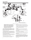
1. Place cylinder on scale platform and connect filler hose.
2. Slide beam weight “H” to tare weight stamped on cylinder.
3. Balance scales to compensate for the weight added by
the filler hose and shutoff valve. On some scales this can be
done by means of a small weight near the beam pivot pin. On
others a suitable weight can be added to scale pan “F”.
4. Add a 100 pounds (45,4 kg) weight (or the net weight
desired) to scale pan “F”, and open the cylinder and hose
valve for trial automatic filling operation.
5. Proceed with filling operation until scale beam rises and
contacts the trip valve stem. The filler valve will close and
the filling operation is complete. This is indicated by the red
button on top of the filler valve. Close the hose shutoff valve
and the cylinder valve.
6. Check weight of full cylinder on another
scale. Balance
weight or the weight in scale pan “F” may have to be
readjusted slightly until the correct cylinder weight is
obtained. Filling accuracy is largely dependent upon the
condition of the scale used with Type N201.
7. After the scales have been checked and adjusted, simply
position the empty cylinder on the scale, connect the filling
hose, slide beam weight “H” to the tare weight stamped on
the cylinder, open the hose shutoff valve and the cylinder
valve, and the N201 will fill the cylinder to the weight added
on the scale pan.
Note
When operating with high pump pressure,
the filler valve may close off, then reopen
for a short spurt and close off again. This
is due to the force of
the incoming liquid
stream. If the proper cylinder weight has
been obtained before the additional spurt,
the operator should immediately close the
hose shutoff valve when the scale beam
contacts the trip valve stem. If the scales
are balanced after the additional spurt, the
operator should wait for this before closing
the hose shutoff valve.
In Case of Trouble
1. If sticking of the main (upper) valve should occur, place a
few drops of oil below the disc holder, Key No.5 in Figure 3.
This can be done with an eye dropper or oil can through one
of the outlet ports. Refer to the disassembly instructions if this
does not correct the situation.
2. If the disc holder wears out quickly, check the outlet
pressure of regulator no. 2. Too high a regulator setting will
cause the disc to fail. Refer to step 4 under “Installation”.
3. If the trip valve stem “B” should stick, remove the lower
trip valve body, and clean out all oil or grease. Polish the
seat in the trip valve body by rotating the eraser end of a
pencil against the seat 10 or 12 times.
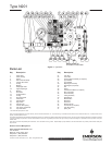
Disassembly
To check disc holder assembly, O-ring, and diaphragms
proceed as follows (numbers in parenthesis refer to Key Nos.
in Figure 3):
1. Remove tubing connection from the angle adaptor in
Type 67/683 (key 30).
2. Mark the valve body (key 17), valve housing (key 2),
and valve head (key 1) so that they can be aligned easily
when reassembling.
3. Remove cap screws (key 22).
4. Separate the valve head (key 1), valve housing (key 2), and
valve body (key 17). Examine the upper and lower diaphragms
(keys 10 and 32). Replace if necessary.
5. Remove orifice (key 3) and unscrew the disc holder
assembly (key 5). Examine and replace if necessary.
6. Remove bushing (key 8) and take out the O-ring (key 7).
Examine and replace if necessary. Put Dow Corning #3 grease
(or equivalent) on the O-ring.
7. Make sure all parts are clean before reassembling.
To reassemble
1. Replace orifice (key 3) in valve head (key 1).
2. Replace O-ring (key 7) and screw in bushing (key 8).
3. Replace disc holder assembly (key 5) and
spring (key 21). Screw the disc holder into the diaphragm
head (key 9).
4. Replace upper diaphragm (key 10) on the valve head
(key 1). Align the valve housing (key 2), spring (key 35),
lower diaphragm assembly (key 32), and valve body (key 17)
so that the cap screws (key 22) can be inserted.
5. Connect tubing (key 39) to angle adaptor in
Type 67/683
(key 30).