


Type N201
2
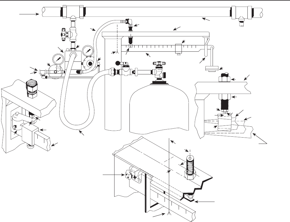
position (full cylinder). To correct this, try
raising the trip valve slightly and retighten
locknuts “D” and “E”. If raising the trip valve
does not correct the situation the 5/8-inch
(16 mm) hole on the scale frame will have to
be drilled closer to the pivot point.
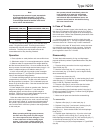
3.A On installations where the slide weight “H” must be
moved to zero, alternate trip valve installation no. 1 can be
made. (This is usually necessary when both 20 pounds
(9 kg) and 100 pounds (45,4 kg) cylinders are to be filled.)
Follow steps 3 (a), (b), (c) and:
d. Place the beam button “J” on the scale beam close
enough to the pivot point to allow the slide weight to move to
zero, see drawing. If there is not enough room to permit this,
either the beam button must be ground down or the user
must make a special beam button.
e. Mount beam bar “K” on the beam button so that it extends
directly under the trip valve. The beam bar can be bent if
necessary and extra length can be cut off.
f. Make certain the beam barely contacts the trip valve
stem when the scale beam is in a level position.
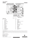
3.B For Fairbanks Morse Type 1124A and 1280A scales,
alternate trip valve installation no. 2 must be made, see drawing.
a. Measure 3-inch (76,2 mm) from the pivot point as shown.
b. Measure 1 1/4-inch (31,75mm) from the scale frame
center line toward the back of the scale.
c. Drill a 5/8-inch (16 mm) hole through the scale frame
at this point.
d. Attach the beam bar “L” to the clamp “M” with two
screws, and attach the clamp to the rear of the scale beam
with two screws.
e. Remove locknut “D” and insert the trip valve through the
5/8-inch (16 mm) hole. Replace locknut.
f. Using locknut “D” and “E”, position trip valve so that
it barely contacts the beam bar ”L” with the scale in a
level position.
4. Connect supply pressure (air or gas) at point “P”.
Recommended supply pressure is at least 30 psig (2,1 bar),
since regulator 2 is set at 30 psig (2,1 bar) outlet pressure.
A 30 psig (2,1 bar) supply is sufficient for pump discharge
pressures up to 350 psig (24,1 bar). Regulator 1 is set at
3 psig (0,21 bar).
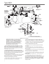
Figure 2. N201 Installation
L
PIVOT
POINT
M
F
BEAM
HORIZONTAL
(LEVEL)
BEAM IN RAISED
POSITION
D
E
STANDARD TRIP VALVE
INSTALLATION
MANIFOLD
SCALE FRAME
H
TRIP VALVE
2
PIVOT
POINT
C
I
P
H
K
J
TRIP VALVE
3
(76,2)
1 1/4
(31,8)
INCH
(mm)
TRIP
VALVE
J
J
BEAM WHEN CYLINDER
IS NOT FILLED
SCALE
FRAME
BEAM STOP
SCALE BEAM
FROM CHARGING PUMP
TRIP VALVE
HOSE
TYPE 201
FILLER VALVE
PILOT VAPOR
PRESSURE FROM
AIR COMPRESSOR
STORAGE TANK,
OR AUXILIARY
PROPANE CYLINDER
SCALE BEAM
FILLING HOSE
APPROX. 1/5
LENGTH OF
SCALE BEAM
ALTERNATE TRIP VALVE INSTALLATION # 2
(FOR TYPE 1124A AND 1280A FAIRBANKS MORSE SCALE)
ALTERNATIVE TRIP VALVE
INSTALLATION #1
A
B