


T
he Mounting Bracket:
To remove the mounting bracket from the Heat
Alarm base, hold the Heat Alarm base firmly and
t
wist the mounting bracket counterclockwise.
The mounting bracket installs onto the junction box.
It has a variety of screw slots to fit most boxes.
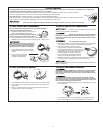
The Power Connector:
The power connector plugs into a power input block on
the Heat Alarm. It supplies the unit with AC power.
• The black wire is “hot.”
• The white wire is neutral.
• The orange wire is used for interconnect.
If you need to remove the power connector, disconnect
AC power at the electrical panel; insert a flat screwdriver
blade between the power connector and the security
tab inside the power input block. Gently pry back the
tab and pull the connector free.
1
2
3
2
9
8
7
3
5
6
4
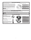
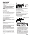
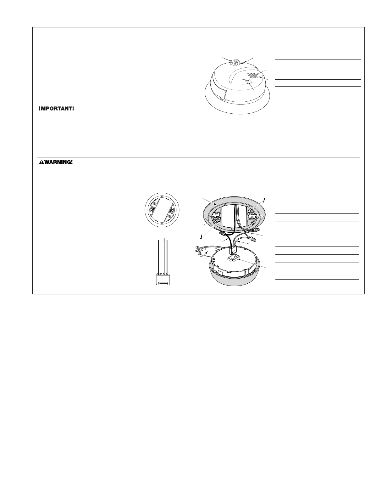
The Parts of This Unit
1 Mounting Bracket
2 Mounting Slots and Screws
3 Locking Pins (break out of bracket)
4 Hot (Black) AC Wire
5 Neutral (White) AC Wire
6 Interconnect (Orange) Wire
7 Latch to Open Battery Compartment
8 Swing-Out Battery Compartment
9 Quick-Connect Power Connector
HOW TO INSTALL THIS HEAT ALARM
THE PARTS OF THIS HEAT ALARM
T
his Heat Alarm is designed to be mounted on any standard wiring junction box to a 4-inch (10 cm) size, on either the ceiling or wall (if allowed by local codes).
Read “Recommended Locations For Heat Alarms” and “Locations to Avoid For Heat Alarms” before you begin installation.
T
ools you will need: • Needle-nose pliers or utility knife
• S
tandard Flathead screwdriver.
F
ixed Temperature and Rate-of-Rise.
T
his Heat Alarm monitors the air and when heat reaches the sensor, it alarms.
The unit will alarm either when the temperature reaches a fixed 135º F (57º C) or
t
he microprocessor detects a 15º F (8.3º C) per minute rate of rise temperature
c
hange. This allows the unit to sense a heat rise and alarm prior to reaching the
fixed temperature of 135º F (57º C), providing quicker response to a potential fire.
H
eat Alarms are intended for use as supplemental safety devices with Smoke
A
larms. Heat Alarms are designed for use in areas where Smoke Alarms
cannot be installed due to temperature and environmental conditions, as in
u
nheated garages and crawl spaces. A Heat Alarm can only give early warn-
i
ng of a developing fire if it is properly installed and maintained and located
where heat can reach it. The unit will not sense gas, smoke or flame. Heat
A
larms cannot prevent or extinguish fires.
T
his Heat Alarm is approved for use in single-family residences. It is NOT
designed for marine or RV use.
T
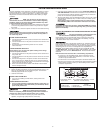
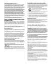
HE COVER OF YOUR HEAT ALARM
1. Power Light, Test/Silence Button
2. Remote Control “Eye”: Aim an infrared
r
emote control at the “Eye” on the Alarm
t
o test or silence the unit. (Works with
most infrared remote controls.)
3. Air Vents
4. (Behind the Cover) Alarm Horn: 85 dB
a
udible alarm for test, alarm, and unit
m
alfunction warning.
5
. Heat Sensor
1
2
3
4
5
HOW THIS HEAT ALARM WORKS
M
ake sure the Alarm is not receiving excessive noisy power. Examples of noisy power could be major appliances on the same circuit, power from a
generator or solar power, light dimmer on the same circuit or mounted near fluorescent lighting. Excessive noisy power may cause damage to your Alarm.
2