


–
15
–
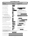
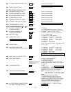
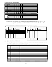
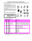
5800 Series Transmitter Input Loop Identification
• All of the transmitters illustrated below have one or more unique factory assigned input (loop) ID codes.
Each
of the inputs requires its own programming zone
(e.g., a 5804's four inputs require four programming zones).
• Transmitter inputs entered as:
"RF" (Supervised RF) Type
send periodic check-in
signals, as well as fault, restore and low battery signals.
The transmitter must remain within the receiver's range.
“UR" (Unsupervised RF) Type
send all the signals that
the "RF" Type does, but the control does not supervise
the check-in signals. The transmitter may, therefore, be
carried off-premises.
"BR" (Unsupervised Button RF) Type
only send fault
signals. They do not send restore or check-in signals.
They will indicate a low battery condition when tested or
activated normally. The transmitter may be carried off-
premises.
Note
: For information on any transmitter not shown
above, refer to the instructions accompanying that
transmitter for details regarding loop numbers, etc
.
UL NOTE
:
The 5802MN, 5802MN2, 5804,
5804BD, 5814, 5816TEMP, 5819,
5819WHS & BRS, 5827BD, and 5850
transmitters are not intended for use
in UL installations
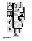
5801
ENROLL AS "UR" OR "RF"
LOOP
1
5802MN
ENROLL AS "UR" OR "RF"
YOU MUST
ENROLL THIS
BUTTON
LOOP 3
LOOP 1
LOOP 2
LOOP 4
LOOP
1
5808
ENROLL AS "RF"
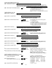
5804
ENROLL
AS "BR"
5817
ENROLL AS "RF"
LOOP
1
(PRIMARY)
2
(AUX. CENTER)
3
(AUX. RIGHT)
LOOP
1
(MOTION)
5890
ENROLL AS "RF"
5816
ENROLL AS "RF"
LOOP
2
(REED)
LOOP 1
(TERMINALS)
5827
SET HOUSE CODE
5827BD
SET HOUSE CODE
5816MN
ENROLL AS "RF"
LOOP
2
(REED)
LOOP 1
(TERMINALS)
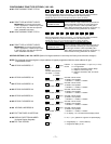
5819
ENROLL AS "RF"
LOOP
2
(REED)
LOOP 1
(TERMINALS)
ALTERNATE
POSITION
FOR LOOP2
LOOP 3
(TERMINALS)
5819S (WHS & BRS)
ENROLL AS "RF"
LOOP
2
(REED)
LOOP 1
(INTERNAL
SHOCK
SENSOR)
LOOP 3
(TERMINALS)
5850 (GBD)
ENROLL AS "RF"
(Green)
(Red)
(Yellow)
5804BD
ENROLL AS "BR"
•
•
•
•
•
•
•
•
•
•
•
•
•
•
•
•
•
•
•
LOOP 3
LOOP 1
LOOP 2
LOOP 4
SET
HOUSE
CODE
YOU MUST
ENROLL THIS
BUTTON
LOOP 3
LOOP 1
LOOP 2
LOOP 4
YOU MUST
ENROLL THIS
BUTTON
LOOP
1
5809
ENROLL AS "RF"
LOOP 2
(REED)
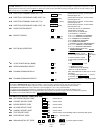
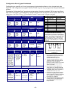
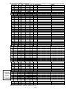
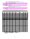
Table of Device Addresses
Address Report
††
Device Programmed by…
00 100 RF Receiver *56 zone programming: input device type entry
03 103 Long Range Radio automatic if output to long range radio field *29 enabled
04 104 4286 Voice Module automatic if phone module access code field *28 enabled
Zone Expanders (4219/4229): *56 zone programming: input device type entry, then:
07 107 module 1 zones 09 - 16
•
automatic if zone no. 9-16 entered as AW type or relay assigned
08 108 module 2 zones 17 - 24
•
automatic if zone no. 17-24 entered as AW type or relay assigned
09
†
109 module 3 zones 25 - 32
•
automatic if zone no. 25-32 entered as AW type or relay assigned
10
†
110 module 4 zones 33 - 40
•
automatic if zone no. 33-40 entered as AW type or relay assigned
11
†
111 module 5 zones 41 - 48
•
automatic if zone no. 41-48 entered as AW type or relay assigned
Relay Modules (4204): *79 output device programming: device address prompt:
12 112 module 1
•
entered at device address prompt
13 113 module 2
•
entered at device address prompt
14
†
114 module 3
•
entered at device address prompt
15
†
115 module 4
•
entered at device address prompt
Keypads: data field programming as listed below:
16 n/a keypad 1
•
always enabled for partition 1, all sounds enabled.
17 n/a keypad 2
•
data field *190
18 n/a keypad 3
•
data field *191
19 n/a keypad 4
•
data field *192
20 n/a keypad 5
•
data field *193
21 n/a keypad 6
•
data field *194
22 n/a keypad 7
•
data field *195
23 n/a keypad 8
•
data field *196
28 n/a 5800TM Module automatic
† These module addresses apply to FA168C only.
††
Addressable devices are identified by “1” plus the device address when reporting. Enter report code for zone 91 to enable
addressable device reporting (default = reports enabled). See field *199 for addressable device (ECP) 3-digit/2-digit identification
touchpad display options.