


–
11
–
✱
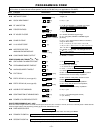
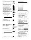
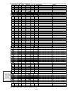
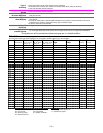
80 OUTPUT DEFINITIONS
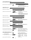
Fill in the required data on the worksheet below and follow the programming procedure in the installation manual as you
enter the data during the displays and prompts that appear in sequence.
Notes:
1.
For Relays, 4229 and 4204 devices are programmed in *79, *80, and *81 modes.
2.
For Powerline Carrier devices (plcd), field
✱
27 must be programmed with a House Code.
3
. Tampers of expansion units cannot be used to operate devices.
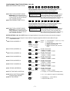
Activation Type and Detail Event (for zone list/activated by)Output
Function
Number
(V20P=1-48)
(V15P=1-24)
Activated by
0=delete
1=zn list
2=zn type
3=zn no.
Zone List
(ZL)
1-8 = list
Zone Type
(ZT)
(see table
below)
Zone No.
(ZN)
00=none
01-64
Partition
Number
(P)
(if using ZT trig)
0 = any
1 = partition 1
2 = partition 2
3 = common
By Zone List
0 = restore
1 = alarm
2 = fault
3 = trouble
By Zone No.
0 = restore
1 = alrm/flt/trbl
Action
0 = off
1 = close 2 secs
2 = stay closed
3 = pulse
4 = toggle
5 = duration 1
††
6 = duration 2
††
Output
Number
FA168C:
1-18
FA148CP:
1-8, 17, 18
Device
Type
R = relay
T = trigger
X = X10
1
2
3
4
5
6
7
8
9
10
11
12
13
14
15
16
17
18
19
20
21
22
23
24
25
26
27
28
29
30
31
32
33
34
35
36
37
38
39
40
41
42
43
44
45
46
47
48
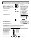
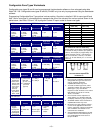
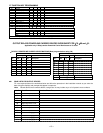
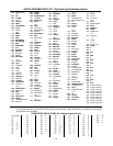
ZONE TYPE/SYSTEM OPERATION – Choices for Zone Types are:
00 = Not Used 05 = Trouble Day/Alarm Night 10 = Interior w/Delay 24 = Silent Burglary
01 = Entry/Exit#1 06 = 24 Hr Silent 12 = Monitor Zone 77 = Keyswitch
02 = Entry/Exit#2 07 = 24 Hr Audible 14 = Carbon Monoxide 90-93 = Configurable
03 = Perimeter 08 = 24 Hr Aux 16 = Fire w/Verification
04 = Interior Follower 09 = Fire 23 = No Alarm Response
Choices for System Operation are:
20 = Arming–Stay 38 = Chime 52 = Kissoff
21 = Arming–Away 39 = Any Fire Alarm 54 = Fire Zone Reset
22 = Disarming (Code + OFF) 40 = Bypassing 58 = Duress
31 = End of Exit Time 41 = **AC Power Failure 60 = AAV Trigger
32 = Start of Entry Time 42 = **System Battery Low 66 = Function key†
33 = Any Burglary Alarm 43 = Communication Failure 67 = Bell Failure
36 = **At Bell Timeout*** 68 = TELCO Line Fault
78 = keyswitch red LED†††
79 = keyswitch green LED†††
Note:
In normal operation mode:
Code + # + 7 + NN Key Entry
starts
Device
Code + # + 8 + NN Key Entry
stops
Device
** Use 0 (any) for Partition No. (P) entry.
*** Or at Disarming, whichever occurs earlier.
† Use *57 Menu mode to assign the function key.
†† Duration is set in program field *177.
††† Device action not used for these choices.