


The basic installation of this Smoke Alarm is similar whether you want
to install one Smoke Alarm, or interconnect more than one Smoke Alarm.
I
f you are interconnecting more than one Smoke Alarm, you MUST read
“Special Requir
ements For Interconnected Smoke Alarms” below before
you begin installation.
ELECTRICAL SHOCK HAZARD. T
urn off power to the area where you
will install this unit at the circuit breaker or fuse box before beginning
installation. Failur
e to turn off the power before installation may result
in serious electrical shock, injur
y or death.
1.
Using wire nuts, connect the power connector to the household wiring.
Impr
oper wiring of the power connector or the wiring leading to the
power connector will cause damage to the Alar
m and may lead to a
non-functioning Alarm.
2. Remove the mounting bracket from the base, and attach it to the
junction box.
3. Plug the power connector into the back of the Smoke Alarm.
4.
Position the base of the Smoke Alarm over the mounting bracket and
turn. The Alarm will remain secure over a wide rotation range to allow for
perfect alignment. When wall mounting, this will allow fine-tuning on the
positioning to compensate for misaligned wall studs and to keep the
wording level. The Alarm can be positioned over the bracket every 120°.
Rotate the Alarm until aligned properly.
5. Check all connections.
ELECTRICAL SHOCK HAZARD. Do not restore power until all Smoke
Alarms are completely installed. Restoring power before installation is
complete may r
esult in serious electrical shock, injur
y or death.
6.
Make sur
e the Smoke Alarm is r
eceiving AC power
. Under normal
operation, the Green power indicator light will shine continuously.
7. If the Green power indicator light does not light, TURN OFF POWER TO
THE JUNCTION BOX and recheck all connections. If all connections
ar
e corr
ect and the Gr
een power indicator still does not light when you
r
estore the power, the unit should be replaced immediately.
8.
Single Station Alarms: Test each Smoke Alarm. Press and hold the
Test/Silence button until the unit alarms.
Interconnected Alarms: Press and hold the Test/Silence button until
the unit alarms. All inter
connected Alarms should sound. The other
Alarms sounding only tests the interconnect signal between Alarms.
It does not test each Alarm’s operation. You must test each Alarm
individually to check if the Alar
m is functioning pr
operly
.
If any unit in the series does not alarm, TURN OFF POWER and r
echeck
connections. If it does not alarm when you r
estor
e power
, replace it
immediately.
SPECIAL REQUIREMENTS FOR INTERCONNECTED SMOKE ALARMS
•
Failure to meet any of the above requirements could damage the
units and cause them to malfunction, removing your protection.
•
AC and AC/DC Smoke Alarms can be interconnected. Under AC
power
, all units will alarm when one senses smoke. When power is
interrupted, only the AC/DC units in the series will continue to send
and r
eceive signals. AC powered Smoke Alarms will not operate.
Interconnected units can provide earlier warning of fire than stand-alone units,
especially if a fir
e starts in a remote area of the dwelling. If any unit in the
series senses smoke, all units will alarm. To determine which Smoke Alarm
initiated an alarm, see table:
During an Alar
m:
On Initiating Alarm(s)
Red LED(s) flashes (flash) rapidly
On All Other Alarms Red LED is Off
After an Alarm (Latching):
On Initiating Alarm(s)
Green LED(s) On for 2 seconds/Off for 2 seconds
On All Other Alarms Green LED(s) On, Red LED(s) is Off
Compatible Interconnected Units
Interconnect units within a single family residence only. Otherwise all house-
holds will experience unwanted alarms when you test any unit in the series.
Interconnected units will only work if they are wired to compatible units and
all requirements are met. This unit is designed to be compatible with:
First Alert
®
Smoke Alarm Models SA4120, SA4121B, SA100B and BRK
Electronics
®
Smoke Alarm Models 9120, 9120B, SC6120B, SC9120B, 7010,
7010B, 100S, 4120, 4120B, 4120SB, RM3 (Relay Module); BRK Electronics
®
CO Alarm Models CO5120BN, CO5120PDBN; BRK Electronics
®
Heat Alarm
Models HD6135F and HD6135FB.
Interconnected units must meet ALL of the following requirements:
• A maximum of 18 compatible units may be interconnected
(Maximum of 12 Smoke Alarms).
• The same fuse or circuit breaker must power all interconnected units.
• The total length of wire interconnecting the units should be less than
1000 feet (300 meters). This type of wire is commonly available at
Hardware and Electrical Supply stores.
•
All wiring must conform to all local electrical codes and NFPA 70 (NEC).
Refer to NFPA 72, NFPA 101, and/or your local building code for further
connection r
equirements.
STAND-ALONE ALARM ONLY:
• Connect the white wire on the power connector to the neutral wire
in the junction box.
•
Connect the black wire on the power connector to the hot wire in
the junction box.
• Tuck the orange wire inside the junction box. It is used for
inter
connect only.
INTERCONNECTED UNITS ONL
Y:
Strip of
f about 1/2” (12 mm) of the plastic coating on the orange
wire on the power connector.
• Connect the white wire on the power connector to the neutral wire
in the junction box.
•
Connect the black wire on the power connector to the hot wire in
the junction box.
•
Connect the orange wir
e on the power connector to the interconnect
wire in the junction box. Repeat for each unit you are interconnecting.
Never connect the hot or neutral wires in the junction box to the orange
interconnect wire. Never cross hot and neutral wires between Alarms.
STAND-ALONE ALARM ONLY:
• If you are only installing one Smoke Alarm, restore power to the
junction box.
INTERCONNECTED UNITS ONLY:
• If you are interconnecting multiple Smoke Alarms, repeat steps
1-5 for each Smoke Alarm in the series. When you are finished,
restore power to the junction box.
6
7
8
4
3
1
5
4
3
1
5
2
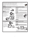
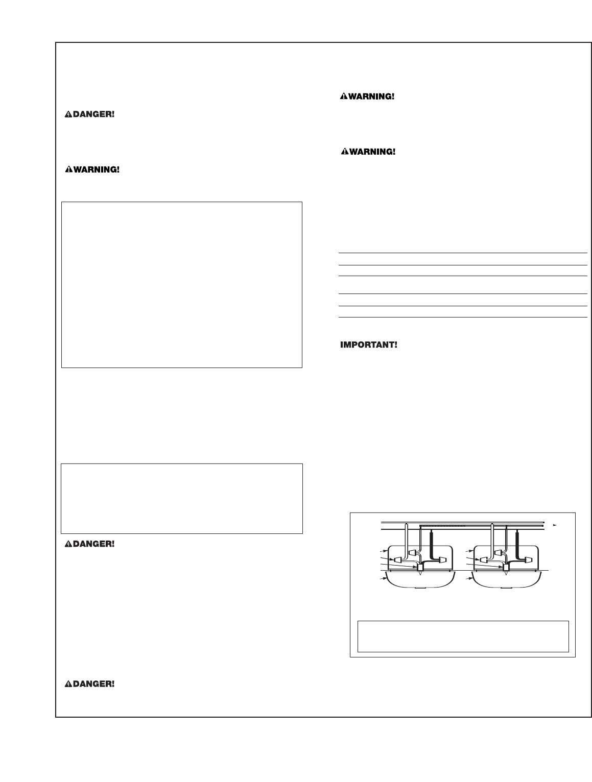
A
B
}
}
A.
Unswitched 120V
AC
60 Hz source
B. To additional units; Maximum = 18 total
(Maximum 12 Smoke Alarms)
1. Smoke Alarm
2. Ceiling or Wall
3. Power Connector
4. Wire Nut
5. Junction Box
6. Neutral Wire (Wht)
7. Interconnect Wire
(Orange)
8.
Hot Wir
e (Blk)
FOLLOW THESE INSTALLATION STEPS
9. For new construction, place supplied dust cover over Alarm to prevent
damage fr
om dust and construction debris. When construction is com-
plete, r
emove cover.
Smoke will not be able to r
each smoke sensor while cover is in place.
Cover must be removed!
3