


P/N: 18122 Page 5 Rev. 1.0
Rev Date: 9/7/07
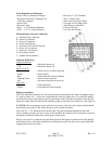
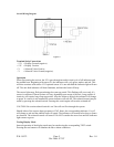
Overall Wiring Diagram
Figure 6
Terminal Strip Connections
- 12V = Display Ground (negative)
+ 12V = Display Positive
+ V = Solenoid Valve Positive
- V = Solenoid Valve Ground (negative)
Operation
When first turning the unit on, the S-2A goes through an audio/visual cycle of all indicators and
the audible horn. Beginning with sensor #1, the indicators will cycle green, amber, and red. This
will then continue with sensor #2. If optional sensor #2 is not installed the indicator light will turn
off. The unit fault indicator will then illuminate, and then the horn will beep.
The sensor lights may flash green during the warm-up period. This flashing will occur only if a
sensor is connected. Warm-up time will vary depending upon usage of the unit. Long periods of
inactivity will require long warm-up periods. After the warm-up period, the indicator will change
to green. It a sensor is not installed the sensor indicator will turn off. The solenoid control may be
tested by pressing the solenoid switch. Pressing this switch again will turn the solenoid off.
CAUTION: Be certain solenoid switch is on! Gas will not flow through the system.
Should either of the sensors detect propane or CNG fumes, the corresponding indicator #1 or #2
will change to red and the audible horn will sound. The indicator will remain red as long as fumes
are detected. The solenoid control will turn off. Do NOT consider the area clear until the indicator
light returns to green.
Testing Display Mode
Internal operation of the display mode may be tested using the corresponding TEST switch.
Pressing the test buttons will simulate the above alarm conditions.