


P/N: 18122 Page 2 Rev. 1.0
Rev Date: 9/7/07
Tools Required and Hardware
• Screw Drivers (Slotted & Phillips) • Hole Saw 2-1/16” diameter
• Electrical Connector Crimping Tool • Two 1 Ampere Fuse
With Wire Stripper • Wire Nuts (#16 Gauge Wire)
• Power Drill • A Length of #16 Gauge Wire
• Electrical Tape • Tape Measure and Pencil
• Drill — 3/4 (19.05mm) Diameter • Crescent Wrench
• Drill — 1/8” (3-17mm) Diameter • 2 in-Line fuse Holder -
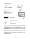
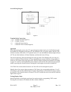
Manual Display Controls / Indicator
A - Solenoid Valve Indicator
B - Sensor #1 Indicator
C - Sensor #2 Indicator
D - Unit Fault Indicator
E - Solenoid Valve On/Off Switch
F - Sensor #1 Test Switch
C - Sensor #2 Test Switch
H - Horn Mute Switch
I - Audible Horn (Internal)
Indicator Definitions
Solenoid Indicator
Green = Solenoid Control on
Off = Solenoid Control off
Sensor #1 & #2
Green = Sensor active, no fumes detected Figure 1
Amber = Sensor failure
Red = Fumes detected! alarm condition
Flashing Green = Sensor warm up period
Off = No sensor detected on power-up
Unit Fault
Off = Unit Functional
Amber = Fault Detected, horn beeping
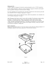
Display Installation
The S-2A should be mounted in a convenient location, preferably at the source of propane usage
(i.e. galley, heater, etc…) where the visual indicators may be readily seen. To install the display,
you must first remove the snap-on bezel by inserting a small, flat blade screwdriver into the slot
located on either side of the bezel and carefully prying up until the bezel snaps free. (See figure 5)
CAUTION: Do not attempt to remove the four (4) screws, which are now exposed which attach
the printed circuit panel to the frame. Doing so will void all warranties.
Next, drill a 2-1 /16” diameter hole into the panel. Slip the instrument through the hole and
secure, making sure that you have access to the terminals for solenoid valve connections, positive
and negative terminal connections and sensor(s) connections.
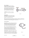
Plug in your sensor to connector one and make positive and negative connections for the display
and solenoid valve. Finish the installation by fastening to panel with four screws (provided) and
snapping bezel back into place.