


3
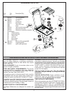
BURNER - TOP VIEW
ORIFICE
INSTALLING YOUR FIRE MAGIC SIDE BURNER (BUILT-IN APPLICATION)
Figure 2
1. CHECKING FUEL AND PROPER ORIFICES: Your Fire
Magic Sideburner is equipped with orifices for natural
gas unless otherwise indicated. For propane gas, smaller
orifices must be installed to avoid hazardous overheating.
The orifice size for Natural Gas is #49 (drill size) and for
Propane Gas, the orifice size is #56 (drill size). Check
the orifice size by removing the burner cap (Item#9F)
and the venturi tube (Item #9C) and looking down through
the hole in the center (see Figure 2 for the location of
the orifice). The drill size is stamped on the orifice. If the
number is not visible you may have to remove the orifice
(as detailed below) in order to read the number stamped
on the side of the orifice.
To remove or change an orifice, you need a 3/8" nut
driver or small wrench. Loosen the orifice using the nut
driver, approaching
from above, or by
approaching from
underneath the burner
using a small wrench.
Remove (check the
number on the side if
needed) and replace
with the correct sized
orifice for your gas type.
Only one propane gas cylinder may be located in an
enclosure. Extra or spare cylinders must be stored
outdoors out of the reach of children and outside of any
building, garage or other enclosed area. READ AND
FOLLOW ALL WARNINGS PROVIDED WITH PROPANE
GAS CYLINDERS. Never locate a cylinder under or
near the barbecue unless sufficient ventilation and
shielding is provided to prevent any heating of the
cylinder, regulator and rubber hose.
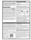
Propane Cylinder Enclosures
To prevent invisible combustible gas from accumulating
in your cylinder enclosure, you must provide adequate
ventilation. This is accomplished by
EITHER of the
following methods. One side of the gas cylinder enclosure
can be left completely open to the outside
OR by
providing four (4) ventilation openings. Two openings are
to be at the cylinder valve level (approx.16” above the
floor) and on opposite walls of the enclosure. Two more
openings must be at the floor level on opposite sides of
the enclosure. The floor level openings must start at the
floor and shall extend no higher than 5” above the floor.
Each opening must have a minimum of 10 square inches
(64.5 cm
2
) of free area. To achieve the proper ventilation,
you may drill a series of holes, omit the grout from
masonry joints or replace a brick with a hardware cloth
screen. If the floor in the cabinet is raised and the space
beneath the cabinet is open to the outside, the lower
ventilation openings may be in the floor.
FOR YOUR SAFETY, you must provide these openings
for drainage, replacement air and cross ventilation of
any storage area exposed to possible leakage from gas
connections, the barbecue or propane cylinder.
2. CONNECTING THE GAS SUPPLY TO YOUR FIRE
MAGlC SIDEBURNER:
a. The burner manifold has a 3/8” male flare fitting gas
inlet elbow. A 3/8" female flare fitting connector nut is
required to hook the gas supply to the burner.
b. Use a stainless steel flex connector to bring the gas
supply from the gas line stub or propane gas tank to the
sideburner manifold. A 3/8" x 24" or 36" flex connector is
suitable for most installations.
CAUTION: Use only a C.S.A. listed stainless steel flex
connector. Do not use a rubber hose or plastic hose
within the enclosure for your sideburner, it will leak
resulting in an explosion and/or serious injury.
NOTE: For installation in a portable barbecue cart, see
the installation instructions packed with the sideburner
shelf and connector kit. Also refer to the portable cart
instruction section for attaching shelves.
c. Be sure the gas supply is 'OFF'. Connect the pipe
adapter fitting supplied with the flex connector to the gas
supply stub. Use pipe joint compound which is resistant
to all gasses on the pipe fitting. Tighten fitting to gas
supply and connector flare nut securely.
Note: pipe joint compound should not be used on flare
fitting connections.
HOUSEHOLD PROPANE GAS SERVICE
Consult your gas supplier for ventilation and regulator
requirements when connecting to a HOUSEHOLD
propane supply.
EXHAUST REMOVAL: When installed under a patio roof,
the side burner area should be under a hood with an
exhaust fan.
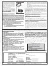
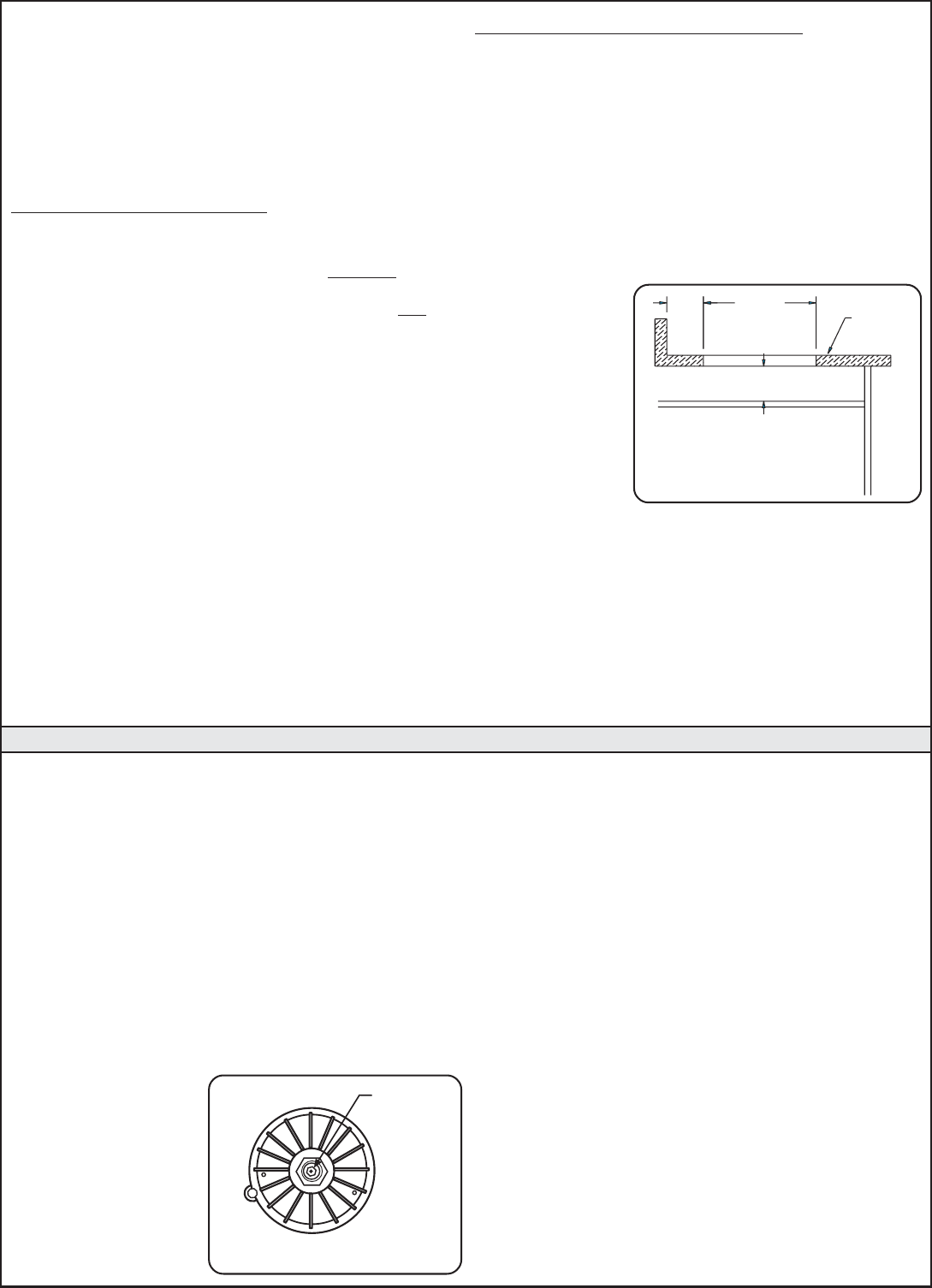
GAS SUPPLY PLUMBING REQUIREMENTS: Rigid 1/2"
black steel pipe is required to conduct the gas supply
into the masonry opening for connection to the unit. Apply
pipe joint compound (resistant to all gasses) to all male
pipe fittings and tighten all joints securely. Do not use
pipe joint com-
pound to connect
flare fittings. The
pipe should enter
enclosure either
from bottom or
from any side at
least 4" below the
countertop (see
Figure 1).
NOTE:Any
protrusion into the
enclosure higher than 4" below countertop will obstruct
the frame and prevent the unit from dropping into place.
SAFETY NOTE: An external valve (with a removable key)
in the gas line is recommended for safety.
GAS SUPPLY AND MANIFOLD PRESSURES:
For Natural Gas - normal 7" water column, minimum
5", maximum 10-1/2". For Propane Gas - normal 11"
water column, minimum 8", maximum 13". A REGULA-
TOR MUST BE PROVIDED AT THE BOTTLE OR GAS
SOURCE FOR USE WITH PROPANE GAS.
Figure 1
6" CLEARANCE
ALSO ALLOW SPACE FOR HOOKUP
SIDE VIEW
4"
14 1/4"
COUNTER
TOP