


page3
WARNING: Never expose eyes or skin to UVC light from any source. Looking directly at the UVC light may cause permanent eye damage or blindness.
Never operate the UV-Aire
™
Air Purifying System out of the plenum. Avoid touching the glass portion of the lamp with your hands.
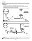
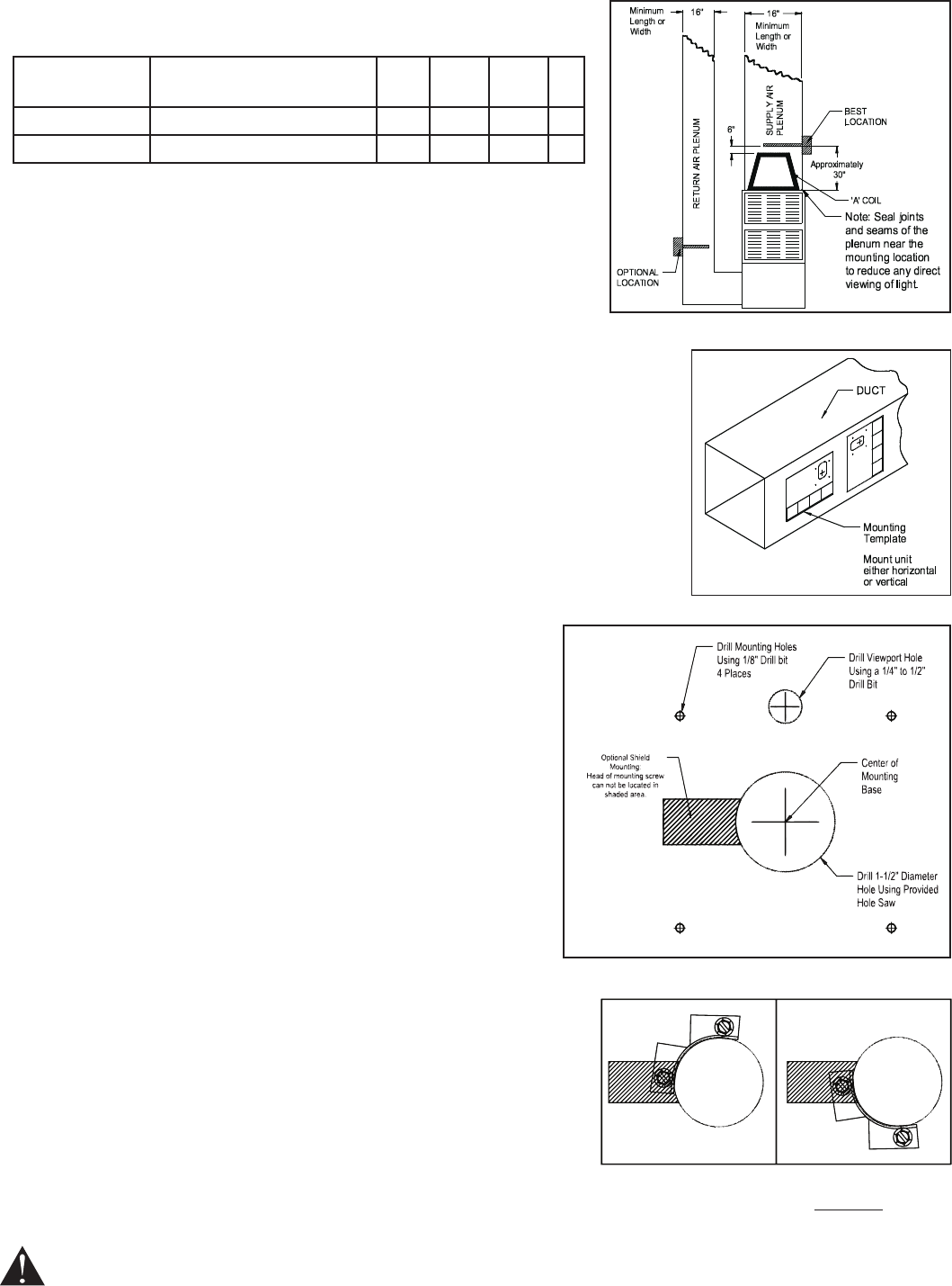
INSTALLATION
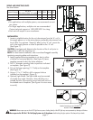
Locate a suitable location for the unit downstream from the 'A' coil in 1.
the supply plenum or in the return plenum; preferably downstream from
theairlter.Foroptimum"cleaning"effectonthe'A'coil,mountthe
unit in the supply plenum as close as possible to the 'A' coil.
(See Figure 1)
CAUTION: Investigate and determine the location of the A coil prior to
drilling holes in duct for mounting unit.
NOTE: For duct board installation, refer to enclosed bagged assembly
containing mounting plate and instructions.
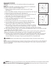
Apply supplied mounting template to air duct in either 2.
a vertical or horizontal position. (See Figure 2) Leave
template mounted to duct for future reference.
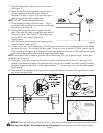
Drill 3.
1
⁄8"diametermountingholesatpositionsindicated
ontemplate.(SeeFigure3)
Cut out the large opening (1-4.
1
⁄2"hole)onthetemplate.
(SeeFigure3)
Using a 5.
1
⁄4"to
1
⁄2"drillbit,drillaviewportholeas
indicatedonthetemplate.(Figure3)
Optional Light Shield: The light shield may be mounted 6.
at virtually any angle. However, when deciding on a
suitable location, the mounting screw head can not be in
the shaded area of template. (See Figure 4 to view areas
to avoid.)
Figure 1
Figure 3
Figure 2
Figure 4
Head of mounting screw CANNOT be
located in shaded area.
Notes:
For applications with multiple systems, we recommend one unit
•
per system.
For larger applications, multiple units are recommended.
•
Contacttechnicalsupportat1-252-522-3031forsizing.
Each unit will require its own transformer.
•
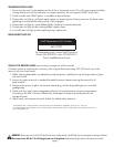
Square Footage
UV-Aire
(For ducts at least 16" wide)
Volts Watts Amps Hz
Up to 2000 1 24 23 1.3 60
4000 2 24 46 2.6 60
SIZING AND SELECTING UNITS
See chart below: