


Page 2
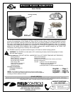
INSTALLATION AND ADJUSTMENT
PLEASE READ COMPLETELY BEFORE BEGINNING INSTALLATION!
CAUTION: The TM-2000 is not to be used on electric furnaces, heat pumps, or in locations where the air
temperature could drop below 40°F. The mounting position of the mounting position of the TM-2000 is very
important. Read all installation instructions prior to installing your TM-2000 humidifier. Save these
instructions for future reference of replacement parts and optional components.
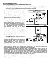
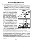
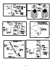
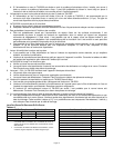
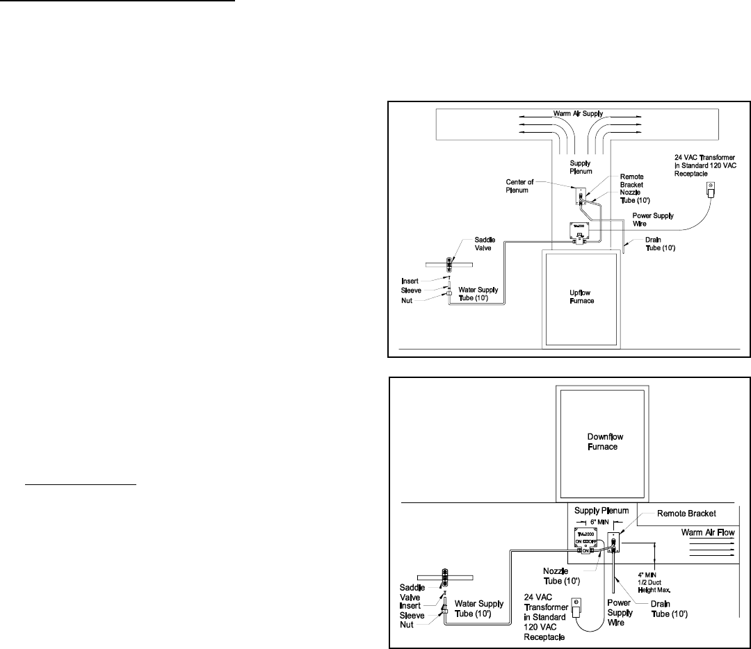
1. Locate the SUPPLY PLENUM of your warm air
furnace. The supply plenum is the main duct of the
furnace that directs heated air to the home. (See
Figures 1-3) A minimum of 120°F is required in the
furnace supply plenum to allow for proper humidifier
operation. Most oil and gas fired furnaces are
capable of providing air flow of this temperature. If
this condition cannot be met, a different type of
humidification system must be considered.
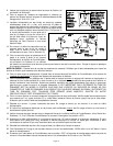
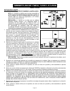
2. Determine the optimal location for the Housing
Assembly (See Figures 1-3, 5 & 8 for typical
installations) by locating the warmest part of the
plenum (close to the outlet of the furnace) that will
satisfy these minimum requirements: (a) 120°F
minimum air flow temperature in the supply plenum,
(b) 1 cubic foot minimum volume surrounding nozzle
tip to prevent spray impingement on duct walls, or
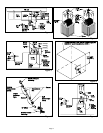
other obstacles. (See Figure 6) In certain
installations, it may be necessary to further extend
the nozzle using an optional Field Controls EK-1
Extender Kit. (See Figure 7) A 45
o
elbow fitting can
also be installed to redirect the spray without
extending the nozzle. If an air conditioning “A-COIL”
with open sides
exists at the furnace outlet, the
Housing Assembly should be located in the area
between the A-COIL and the furnace outlet. (See
Figures 4, 5 & 8)
CAUTION: Use extreme caution when drilling or
cutting any holes in the furnace plenum in order
to avoid damaging the A-coil.
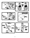
3. Following the instructions printed on the Housing
Mounting Template, attach it to the plenum at the
location determined in Step 2. MOUNT THE
TEMPLATE RIGHT SIDE UP ON A VERTICAL
SURFACE ONLY, ON THE SIDE OF THE PLENUM.
4. Cut and drill or punch holes in the plenum as indicated on the template, and completely remove the template
when finished.
5. Carefully mount the TM-2000 Housing Assembly to the plenum using the four #8-15 x 3/4” long hex head
sheet metal screws. Take care to avoid damage to the thermal sensing element.
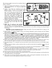
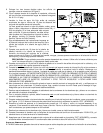
6. Determine an appropriate location for the Remote Nozzle Bracket Assembly, being careful to maintain the
minimum distances from the Housing Assembly and adjacent plenum walls and other structures, as shown in
Figures 1-3. BE SURE THAT THE NOZZLE IS LOCATED DOWNSTREAM OF THE HOUSING ASSEMBLY, IN
SUCH A WAY THAT THE MIST WILL NOT BE DIRECTED TOWARDS THE HOUSING ASSEMBLY. THE
NOZZLE ASSEMBLY SHOULD BE MOUNTED RIGHT SIDE UP ON A VERTICAL SURFACE, ON THE SIDE
OF THE PLENUM, WITH THE NOZZLE DIRECTLY ABOVE THE DRIP GUARD.
7. Following the instructions printed on the Remote Bracket Mounting Template, attach it to the plenum at the
location determined in Step 6.
8. Cut and drill or punch holes in the plenum as indicated on the template, and completely remove the template
when finished.
Figure 2
Figure 1