


Page 2
INSTALLATION
1. Carefully unpack the unit. Check for damage and make sure
all of the required parts are included. The units are thoroughly
tested before packing to insure safe delivery and operation. If
there is any sign of damage due to shipment return it to the
place of purchase for repair or replacement.
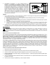
2. Choose a mounting location near the air conditioner or
furnace. The pump must be mounted level and the inlet must
be below the lowest drain. The unit has two brackets built into
the deck that can be used to attach the unit to a wall or to the
side of the appliance with installer supplied fasteners.
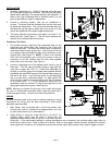
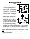
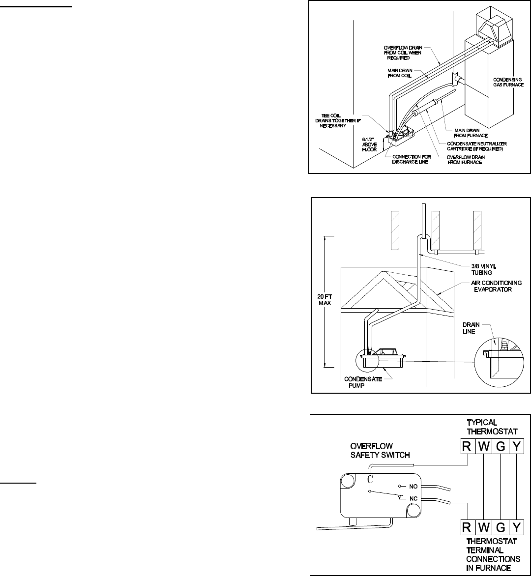
3. The pump should be mounted so the deck is at least 6 1/2"
above the floor. (See Figure 1) This will allow clearance for
the tank to be removed later for cleaning.
CONNECTING THE PIPING
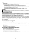
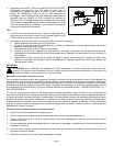
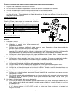
1. Run flexible tubing or pipe from the condensate drain on the
evaporator pan and/or drain from furnace to one of the inlet
holes on the pump. This drain line should have a continuous
downward slope to allow gravity flow. Cut the end of the line
at an angle so the end does not close off on the bottom of the
pump's tank. (See Figure 2) NOTE: If there is an overflow
drain from the evaporator pan or from the furnace, it may be
necessary to tee the overflow and the main drain together
before they enter the pump. (See Figure 1)
2. Connect a discharge line to the barbed check valve on top of
the pump. This line may be flexible tubing or rigid pipe, but
must be no larger than 3/8" I.D. Extend the discharge line
straight up from the pump to the highest point possible without
exceeding the head/GPH capacity of the pump before directing
the line to the drain. From this high point, run the discharge
line to a drain with a downward slope. For best results, the
drain should be below or approximately level with the bottom
of the pump tank. If it is not possible to slope the line
downward, make an inverted "U" trap at the high point of the
discharge line above the pump. (See Figure 2)
NOTE: Although not needed for this pump, local codes may require
the use of a condensate neutralizer when using this pump with a
condensing gas furnace. Consult local codes for guidelines.
WIRING
Shut off electrical power at the fuse box before making any wiring
connections. All wiring must be done according to local and/or
applicable national codes.
1. Main Power: Unit is provided with a 6 foot long power cord.
Connect this cord to a constant line voltage source, not a fan
or other device that may run intermittently.
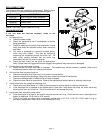
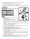
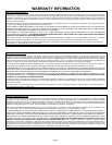
2. Safety Switch: If using the model 20+ULS or 20+ULST, the
overflow safety switch may be wired in series with the
appliance's thermostat to shut off the unit in the event that the
pump fails. In the case where heating or cooling requirements are a necessity, the overflow safety switch may be
wired into an alarm circuit. Refer to Figure 3 for wiring. Note: In most cases, use the normally closed (NC) contacts
when used with a furnace or air conditioner and use the normally open (NO) contacts when used to trigger an alarm.
Figure 1
Figure 2
Figure 3