


Product Specifications
3
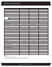
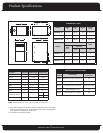
Specifications subject to change without notice.
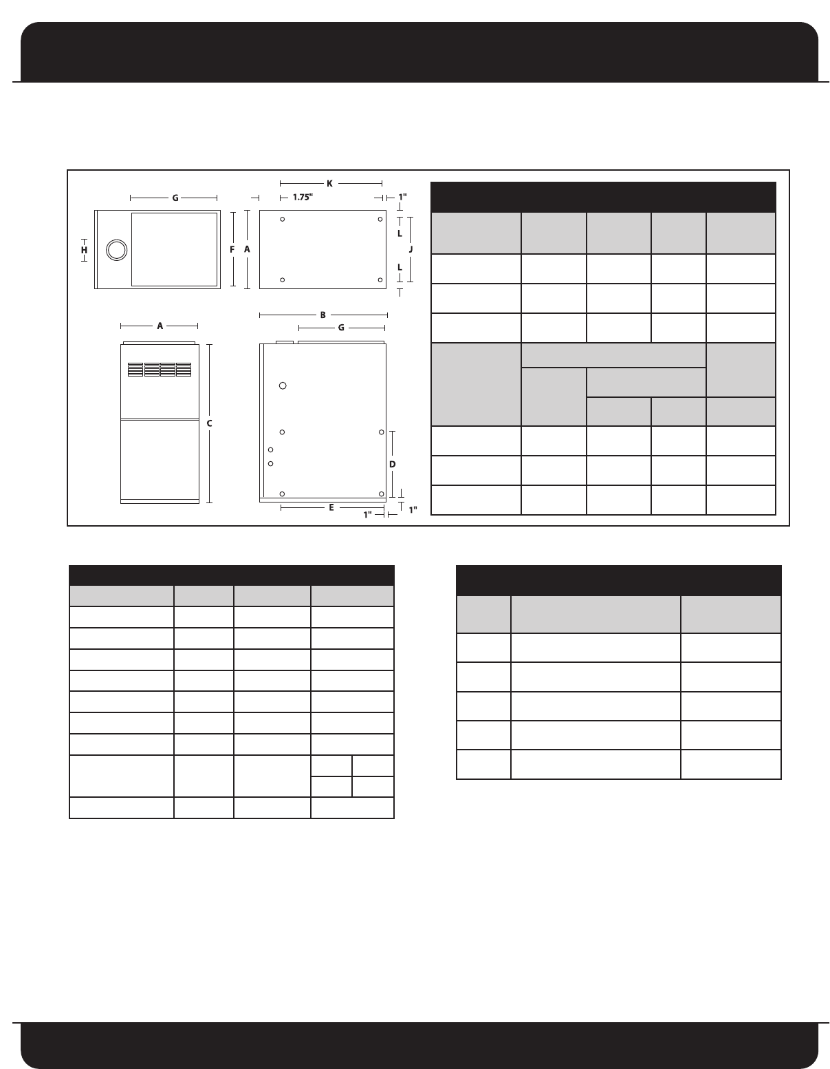
DIMENSIONS (inches)
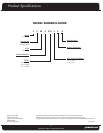
MODEL
WIDTH
A
DEPTH
B
HEIGHT
C
SUPPLY
F x G
FV80A070-4A 17 1/2 28 1/4 35 16 1/2 X 19
FV80A085-4A 20 1/2 28 1/4 35 19 1/2 X 19
FV80A115-5A 22 28 1/4 35 21 X 19
MODEL
RETURN
VENT
SIDE
D x E
BOTTOM
J x K L H
FV80A070-4A 14 x 22 14 1/2 x 22 1 1/2 4
FV80A085-4A 14 x 22 16 x 22 2 1/4 4
FV80A115-5A 14 x 22
2
19 x 22 1 1/2 5
1
CLEARANCE TO COMBUSTIBLES (inches)
SURFACE UPFLOW DOWNFLOW HORIZONTAL
Top 1 0 2
Front 3 1/2 3 1/2 3 1/2
Flue C-Vent 6 6 6
Flue B-Vent 1 1 1
Back 0 0 0
Side or End 0 0 1
Floor 0 0 0
Supply Air Plenum 1 1
Top End
3 1
Return Air Plenum 0 0 0
FIELD-INSTALLED ACCESSORIES
PART
NUMBER
DESCRIPTION
MODEL
USED WITH
30482 Natural to LP gas conversion kit All
30551 LP to Natural gas conversion kit All
30476 Combustible Floor Sub-base Downflow Only
30553 High Altitude Kit - US All
30552 High Altitude Kit - Canada All
1.
V
ent and combustion air diameters may vary depending upon vent length.
Refer to the latest editions of the National Fuel Gas Code. Field supplied 5"
to 4" reducer kit required for model 115-5.
2. Two return air openings required.
NOTE: Combustible floor kit required for the downflow configuration