


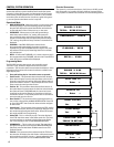
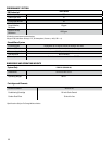

Figure 4. Reject Y-Connector Detail
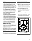
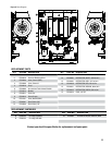
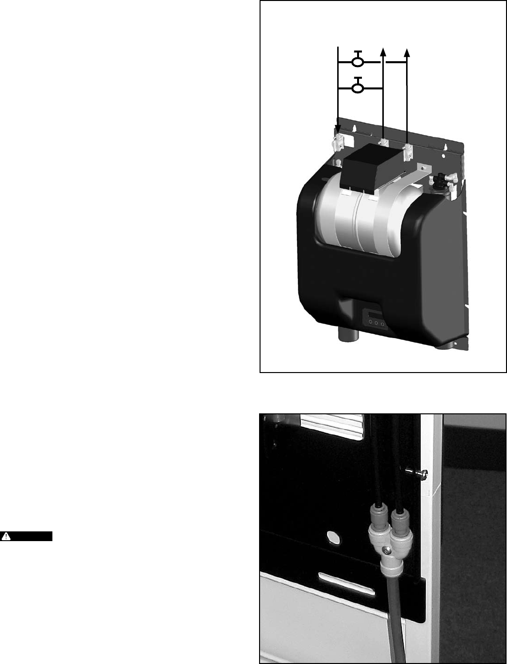
Figure 3. Inlet and Outlet Connections
3
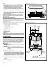
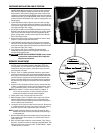
Refer to 3. Figure 1 for mounting bracket details. Position the top
row of holes 1-9/16" inches below the top of the processor when
installed. Install the wall mount bracket to a suitable vertical
surface. Use no less than 4 - #12 fasteners to secure the bracket
to the surface.
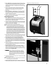
Prepare to attach the processor to the wall mount bracket. 4.
Lift the processor and “hook” the metal lip of the processor
backplate over the top edge of the wall mount bracket.
Go to step 6.
Measure and install 2 - #12 fasteners on 16" centers to engage 5.
the top edge of the processor backplate - leave 1/4" gap. Lift
the processor and “hook” the key-hole slots on the processor
backplate. Tighten the 2 fasteners.
Install 2 - #12 minimum fasteners in the 2" wide slots along the 6.
bottom edge of the processor backplate.
Piping/Tubing Connections
Refer to 1. Figure 2 and the drawing on Page 14 for general views
of the piping, with a description of major components and
connection points. These major components and connections
will be referred to in the following steps.
A parts kit has been provided, which includes valves and tees to 2.
configure a system by-pass. Assemble the parts to the system
using the example shown in Figure 3.
Prepare the plumbing to accept the RO system. 3.
NOTE: The product water tubing/piping and associated fittings
connecting the RO product outlet to the equipment being
serviced
should be food grade material that meets NSF
Standard 51 or 61 with a minimum pressure rating of 100-PSI.
The product water may react with metal piping, creating a
corrosive condition, in addition to imparting an objectionable
taste. Plastic pipe or reinforced tubing are generally very
good choices for RO water
distribution materials. The size of
the product water tubing/piping
should be 3/8" ID minimum.
Distances of 25 feet or greater
from the RO to the equipment
being serviced should be 1/2" ID minimum.
Shut-off the supply of water to the existing filtration system, and 4.
relieve pressure. Connect a line from the treated water outlet of
the filtration system to the inlet of the ENVI-RO system.
Connect the appropriate size and type of tubing/piping and 5.
associated fittings to the corresponding ENVI-RO outlet
connection. Route the line(s) to the equipment being serviced
(i.e.; espresso, coffee, etc.). Close the inlet, outlet and by-pass
valves. Apply pressure to the existing filtration system and place
it back into service.
Check the 6. storage tank pre-charge pressure. It should only be
checked and adjusted when the storage tank is empty. A 30 psi
pre-charge pressure is required.
Connect a 3/8" OD tube to the reject Y-connector (labeled 7.
WASTE) located in lower right corner of processor. Route the
other end of the tubing to a drain nearby, securing it properly.
Allow an air gap at the drain, following any applicable local and
national codes. See Figures 2 and 4.
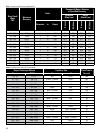
WARNING
Refer to “Reject to Drain, Maximum” under RO
Production in the Performance Table (page 8) to
determine the maximum gallon per minute waste
flow rate. Verify drain has ample capacity for this
waste flow, plus all other sources of waste flow
sharing this drain.
Locate the needle valve from the parts kit. Attach a short section 8.
of 3/8" tubing to this valve.
NOTE: This assembly will be used to adjust the system recovery in
the following section, then removed.
Remove the 3/8" tube from the reject Y-connector and install the 9.
needle assembly between the reject Y-connector and 3/8" tube.
INLET
STEAMER
COFFEE