


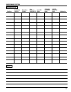
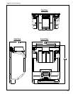


20.0 508
5.0 127
3.1 80
16X .33
THRU
8.4
17.8 452
16.6 422
15.4 391
14.2 361
4.2 107
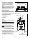
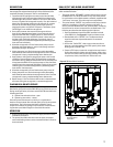
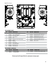
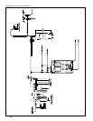
Low TDS
Outlet
(Steamer)
Inlet
(From Filter System)
Reduced TDS
Outlet
(Coee)
ENVI-RO
System
2SR-BW
Conditioning
Cartridge
MR-600
RO Cartridge
RO Reject
(3/8" John
Guest) route
to drain
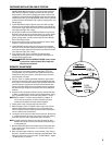
Figure 1. Wall mount bracket.
Figure 2. ENVI-RO Assembly.
2
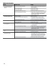
NOTES:
Please read this manual prior to installing and operating the •
system.
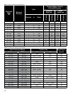
Incoming water supplies that do not meet these requirements •
may need additional pre-treatment prior to the system. System
performance may be affected if requirements are not met,
including system output production and cartridge change-out
frequency.
Consult with your local building inspector for approval and •
required permits to install this system. Additional equipment, such
as back-flow prevention devices, seismic restraint equipment, air
gaps, etc., may be required. Completed installation must meet all
local and national codes.
Do not connect the ENVI-RO™ system after any water filtration
system, unless specifically provided or specified for use with the
ENVI-RO™ system.
UNPACKING AND INSPECTION
The ENVI-RO™ includes all the necessary fittings for installation.
Lengths of 3/8" tubing have been provided for connecting to the
wastewater/drain connection. Supply lines and distribution piping/
tubing are not included.
The ENVI-RO™ system is packaged as a complete unit in one carton.
At a minimum, you should have the following:
Plate mounted processor assembly including:1.
Dual-head Pump •
Cartridge Heads •
Controller & Power Supply•
Storage Tank •
Wall Mount Bracket2.
MR-600 RO cartridge 3.
2SR-BW Cartridge4.
Parts Kit5.
Inspect the carton for damage. Report any damage to freight carrier
immediately and retain all packaging materials. Carefully unpack and
inspect each item.
SYSTEM ASSEMBLY
Locate the system in an area that is convenient to the inlet water
supply and drain facilities, with access for routing the product water
tubing/piping to the equipment. Install in a dry location, away from
all forms of corrosive and/or flammable materials. Consider ease
of access for servicing when selecting a location. Evaluate the
mounting surface for its ability to properly support the weight of the
processor when in operation (Approximately 90 pounds).
WARNING
Do not use screws smaller than #12 for mounting the
processor.
WARNING
Mounting surface may require reinforcement to
support processor safely. Hollow walls, drywall and
other non-structural surfaces are not suitable unless
reinforced.
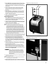
Processor Assembly Mounting
The ENVI-RO system has been provided with a wall mount 1.
bracket to allow greater installation flexibility and ease of
processor placement. If the wall mount bracket is not suitable for
this specific application, the processor backplate has 4 mounting
holes (2 keyhole slots, 2 standard) on 16" centers for securing it
directly to a vertical surface.
Refer to 2. Figure 7 (page 13) for dimensional information. Use
this as your guide to determine the wall mount bracket and/or
processor location. If NOT installing the wall mount bracket go
to step 5.
continued on the next page . . .
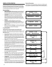
Floor Drain
Maintain air-gap per local and national codes
Position top line of mounting holes 1-9/16” above
the top edge of backplate