


JOHNSON CONTROLS
8
FORM 145.32-IOM1 (908)
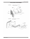
SEPARATION OF UNITS
The 2 through 5 ton units are provided with refrigerant
shut-off valves to allow the evaporator and condenser
sections to be eld split - without the necessity of re-
claiming the entire unit refrigerant charge.
The evaporator and condenser sections may be sepa-
rated by performing the following procedure:
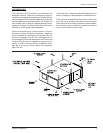
1. Close all refrigerant shut-off valves, on both suction
and liquid lines. There are four valves in a single
compressor model, and a total of eight valves in the
dual compressor models. Valves are not a back-
seating design. Caps are wrench tight. Remove
caps and turn stem clockwise to seat in the closed
position.
2. Use the valve access ports to reclaim the refrigerant
trapped in the lines between the pairs of shut-off
valves.
3. Cut the refrigerant line sections between the pairs of
shut-off valves. It is recommended to make this out
where accessibility is greatest - in the condensing
section of the unit. This will allow best access for
reconnection, or attachment of an extended line
set in the case of a split system.
4. Remove the interconnecting wiring between the
evaporator and condenser electrical panel. Dis-
connect the wire terminations in the condenser
electrical panel, and pull the excess wire into the
evaporator panel.
5. Remove the threaded wire bushing connecting the
two electrical panels.
6. Remove the unit top-joining strip; take care to re-
move only those screws which attaches the joining
strip to the evaporator and condenser cabinets.
7. Remove the two side cross-member angles.
8. Carefully pull the evaporator section away from the
condenser section. Take care not to damage the
short lengths of refrigerant tubing extending into
the condenser section.
The separated evaporator and condenser modules may
now be individually moved to the proposed installation
site for re-assembly, or separately located for split ap-
plications.
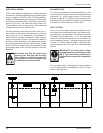
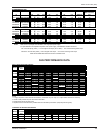
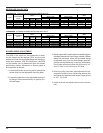
INTERCONNECTING REFRIGERANT TUBING
- SPLIT INSTALLATION
After the evaporator and condenser sections have been
mounted, the interconnecting refrigerant tubing can be
fabricated. Line sizing recommendations shown in the
accompanying table are suitable for most applications.
Consult sales ofce for applications outside the speci-
ed guidelines.
Route refrigerant tubing for minimum linear length, and
minimum number of bends and ttings. Use long radius
elbows for all 90-degree bends, except oil traps. Traps
should be constructed from short radius street elbows,
in order to keep the trap as small as possible. All brazing
should be done using a 2 to 8 psig dry nitrogen purge
owing through the pipe being brazed.
Once the brazing operation of refrigeration lines is com-
pleted, the eld-brazed connections must be checked for
leaks. Pressurize the system through the shut-off valve
ports with dry nitrogen to a minimum of 400 psig. Use
soap bubbles or alternate methods of leak-checking all
eld brazed joints. After completion of the leak check,
evacuate the interconnecting lines to hold a 350-micron
vacuum. If gauge pressure rises above 500 microns in
one minute, then evacuation is incomplete or the system
has a leak.
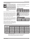
Additional refrigerant (R-410A) must be added to the
system due to the extended refrigerant lines. Calculate
the amount of additional refrigerant required as fol-
lows:
1. 5/16 in OD liquid line - add 0.40 oz per linear foot
2. 3/8 in OD liquid line - add 0.60 oz per linear foot
3. 1/2 in OD liquid line - add 1.20 oz per linear foot
4. 5/8 in OD liquid line - add 1.80 oz per linear foot