


FORM 145.32-IOM1 (908)
15
JOHNSON CONTROLS
START-UP AND OPERATION
Prior to starting unit for the rst time,
turn the thermostat system switch to
OFF - or raise the cooling setpoint to
the highest temperature, to prevent the
unit from starting. Close the electrical
disconnect switch. This will energize the
compressor crankcase heater(s). WAIT
A MINIMUM OF FOUR HOURS BEFORE
STARTING THE SYSTEM. This period will
allow the crankcase heater to vaporize
any liquid refrigerant in the compressor
crankcase.
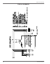
Start unit and check rotation of fans and compressors.
Scroll compressors will only compress in one rotational
direction. Three phase compressors will rotate in either
direction depending upon phasing of the power. Since
there is a 50-50 chance of connecting power in such a
way as to cause rotation in the reverse direction, it is
important to ensure proper rotation direction is achieved
when the system is installed and operated.
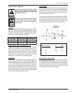
Verication of proper direction is made by observing
that suction pressure drops and discharge pressure
rises when the compressor is energized. Reverse rota-
tion also results in an elevated sound level as well as
substantially reduced current draw.
There is no negative impacts on durability caused by
operating three phase Scroll compressors in the re-
versed direction for a short period of time (less than one
hour). However, after several minutes of operation the
compressors internal protector will trip.
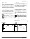
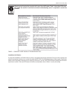
Ref. Charge 2 TON 3 TON 4 TON 5 TON
No. of Circuits 1 1 1 1
Per Circuit (lb) 7.625 8.125 11.188 10.938
ALL MODELS
High Low
Cut Out (PSIG) 600 55
Cut In (PSIG) 450 75
If opposite rotation is needed, disconnect and reverse
any two leads of the three phase supply. Reconnect
power and observe for correct rotation.
Observe unit operation and check for unusual noise or
vibration.
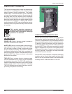
REFRIGERANT CHARGES
The Air Conditioning section of this
equipment is charged with R-410A; a hi-
pressure refrigerant. Only qualied techni-
cians, using appropriately pressure-rated
test instruments, should perform trouble-
shooting or service on this equipment.
PRESSURE SWITCH SETTINGS
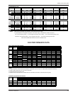
RECCOMENEDED REFRIGERANT LINE SIZES
UNIT SIZE
LESS THAN 60 LINEAR FEET 60 - 150 LINEAR FEET
LIQUID LINE SUCTION LINE LIQUID LINE SUCTION LINE
2 TON 5/16 5/8 3/8 3/4
3 TON 3/8 3/4 3/8 7/8
4 TON 3/8 7/8 1/2 1-1/8
5 TON 3/8 1-1/8 1/2 1-1/8
8 TON 2 X 3/8 2 X 7/8 2 X 3/8 2 X 1-1/8
10 TON 2 X 3/8 2 X 1-1/8 2 X 1/2 2 X 1-1/8
12 TON 2 X 1/2 2 X 1-1/8 2 X 1/2 2 X 1-3/8
15 TON 2 X 1/2 2 X 1-1/8 2 X 5/8 2 X 1-3/8
NOTES: - Maximum Suction Lift 60 FT
- Maximum Liquid Line Rise 40 FT (measured from condensing unit level).
- Liquid Line Solenoid Valve required on systems over 100 linear feet.
- Suction Accumulator(s) required on systems over 125 linear feet.