


035-17233-000-C-0702
Unitary Products 7
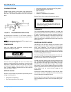
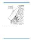
CONDENSATE DRAIN
Plumbing must conform to local codes. Use a sealing com-
pound on male pipe threads. Install a condensate drain line
from the 1" NPT female connection on the unit to an open
drain.
An alternate drain connection (1" NPT female coupling) is
provided inboard on the same centerline as the exterior loca-
tion.
NOTE:
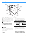
The condensate drain line MUST be trapped to pro-
vide proper drainage. See Figure 4.
COMPRESSORS
Units are shipped with compressor mountings factory-
adjusted and ready for operation.
FILTERS
Two-inch filters are supplied with each unit. Filters must
always be installed ahead of the evaporator coil and must be
keptcleanorreplacedwithsamesizeandtype.Dirtyfilters
will reduce the capacity of the unit and will result in frosted
coils or safety shutdown. Minimum filter area and required
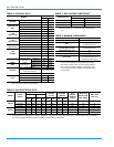
sizes are shown in Table 6.
SERVICE ACCESS
Access to all serviceable components are provided by the fol-
lowing removable panels:
• Compressor compartment
• Gas Heat compartment (Two panels)
• Side Supply & Return Air compartments (Two panels)
• Blower compartment (Three panels)
• Main control box
• Filter compartment
• Outdoor Air compartment (Two panels)
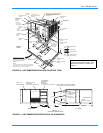
Refer to Figure 10 for location of these access panels.
THERMOSTAT
The room thermostat should be located on an inside wall
approximately 56" above the floor where it will not be subject
to drafts, sun exposure or heat from electrical fixtures or
appliances. Follow manufacturer's instructions enclosed with
thermostat for general installation procedure. Seven color
coded insulated wires (#18 AWG) should be used to connect
thermostat to unit.
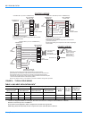
POWER AND CONTROL WIRING
Field wiring to the unit must conform to provisions of the
National Electrical Code, ANSI / NFPA No. 70 (latest edition)
and/or local ordinances. The unit must be electrically
grounded in accordance with N.E.C. and/or local codes. Volt-
age tolerances which must be maintained at the compressor
terminals during starting and running conditions are indicated
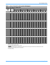
on the unit Rating Plate and Table 2.
The internal wiring harness furnished with this unit is an inte-
gral part of a ETL design certified unit. Field alteration to com-
ply with electrical codes should not be required.
A fused disconnect switch should be field provided for the
unit. The switch must be separate from all other circuits. Wire
entry at knockout openings require conduit fittings to comply
with NEC and/or local codes. Refer to Figure 10 for installa-
tion location. If any of the wire supplied with the unit must be
replaced, replacement wire must be of the type shown on the
wiring diagram and the same minimum gauge as the
replaced wire.
Electrical line must be sized properly to carry the load. Each
unit must be wired with a separate branch circuit fed directly
from the meter panel and properly fused.
Refer to Figure 5 for typical field wiring and to the appropriate
unit wiring diagram for control circuit and power wiring infor-
mation.
FIGURE 4 : RECOMMENDED DRAIN PIPING
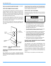
Do Not loosen compressor mounting bolts.
Make sure that all screws and panel latches are
replaced and properly positioned on the unit to
maintain an air-tight seal.