


035-17233-000-C-0702
6 Unitary Products
combustion and ventilation air in accordance with Section
5.3, Air for Combustion and Ventilation of the National Fuel
Gas Code, ANSI Z223.1 (in U.S.A.) or Sections 7.2, 7.3 or
7.4 of Gas Installation Codes CAN/CGA-B149.1 and .2 (in
Canada) and/or applicable provisions of the local building
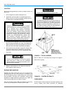
codes. Refer to Table 8 for the clearances required for
combustible construction, servicing, and proper unit
operation.
DUCTWORK
Ductwork should be designed and sized according to the
methods in Manual Q of the Air Conditioning Contractors of
America (ACCA).
A closed return duct system shall be used. This shall not pre-
clude use of economizers or outdoor fresh air intake. The
supply and return air duct connections at the unit should be
made with flexible joints to minimize noise.
The supply and return air duct systems should be designed
for the CFM and static requirements of the job. They should
NOT be sized to match the dimensions of the duct connec-
tions on the unit.
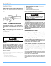
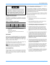
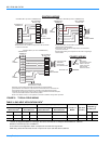
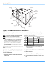
Refer to Figure 10 and 12 for information concerning side and
bottom supply and return air duct openings.
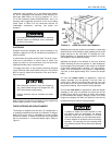
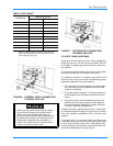
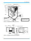
FIXED OUTDOOR AIR INTAKE DAMPER
This damper is shipped inside the return air compartment. It
is completely assembled and ready for installation. A damper
baffle inside of the hood is adjustable to provide variable
amounts of outdoor air intake on units that are not provided
with an economizer or a motorized damper option. Refer to
Figure 3.
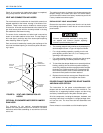
Gasketing and mounting screws are provided in a parts bag
attached to the hood assembly. Apply gasketing to the three
flange surfaces on the hood prior to installing the hood.
Extend gasketing 1/4" beyond the top and bottom of the two
side flanges to insure adequate sealing.
Adjusting the damper to the desired air flow may be done
before mounting the hood into position or (after installation)
by removing the front hood panel or the screen on the bottom
of the hood. Damper baffle in position 1 will allow approxi-
mately 10% recirculated air flow, position 2 approximately
15% and, to allow approximately 25%, remove the damper
baffle.
On units with bottom return air applications, install the
damper assembly over the opening in the side return air
access panel. Remove and discard the opening cover and
the covering over the hood mounting holes (used for ship-
ping) before installing. Secure with the screws provided.
On units with side return air applications, install the damper
assembly on the return air ductwork as close to the unit as
possible. Cut an opening 16" high by 18" wide in the ductwork
to accommodate the damper. Using the holes in the hood
flanges as a template, drill 9/64" dia. (#26 drill) holes into the
ductwork and secure with the screws provided.
Do not permit overhanging structures or shrubs to
obstruct outdoor air discharge outlet, combustion
air inlet or vent outlets.
When fastening ductwork to side duct flanges on
unit, insert screws through duct flanges only. DO
NOT insert screws through casing.
Outdoor ductwork must be insulated and water-
proofed.
FIGURE 3 : FIXED OUTDOOR AIR DAMPER
If outdoor air intake will not be required on units
with bottom return air applications, the damper
assembly should still be mounted on the side
return air access panel, per the instructions above,
to insure moisture is not drawn into the unit during
operation. The covering over the mounting holes
only need be removed. Do not remove the opening
cover.