


WARNING: Install a check valve and/or a Hartford
loop AFTER the heat pump pool heater and
BEFORE any chlorinating devices. Install any auto-
matic chemical feeders AFTER the heat pump pool
heater. Improper installation of any type of auto-
matic chemical feeders can result in serious
damage to, or premature failure of, the heat
pump pool heater and will void the heat pump
pool heater warranty.
Water Connections
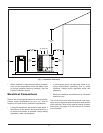
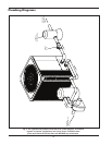
1. Connect the heat pump pool heater in the return
water line between the filter and the pool/spa. See
the Plumbing Diagrams beginning on page 12.
2. Connect the filter outlet to the fitting marked
WATER IN at the bottom front of the unit.
3. Connect the fitting marked WATER OUT to the
return piping to the pool/spa. Unit inlet/outlet con-
nection fittings are 2-inch PVC unions.
Water connections from the unit to the main return
line can be PVC pipe or flexible pipe approved for
the purpose and, in either case, should be at least
equal in size to the main pool/spa circulation pip-
ing.
4. In cold weather (freeze zone) areas, shutoff valves
(ball or gate type) must be installed at the unit inlet
and outlet to facilitate service and cold weather
drain-down.
5. Operate the pump and check the system for leaks.
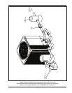
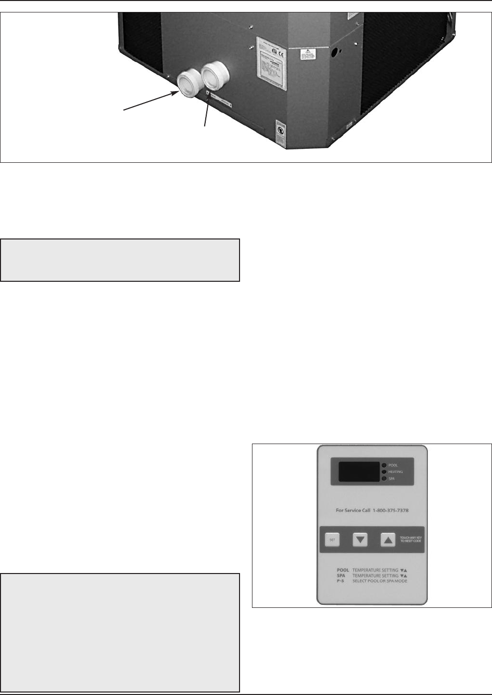
CAUTION: The heat pump pool heater inlet and
outlet connections are NOT interchangeable. They
must be connected as instructed below.
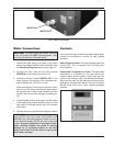
Fig. 2: Water Connections
WATER IN
WATER OUT
Controls
Your heat pump pool heater incorporates digital safety
controls and indicators to ensure its safe, reliable
operation.
Water Pressure Switch: Prevents operation when the
pump is OFF. The unit requires 5 psi (0.73 kPa) mini-
mum pressure.
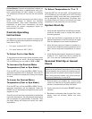
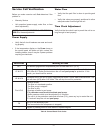
Digital Water Temperature Control: The pool water
temperature is controlled by the heat pump pool
heater’s digital control system, which gives you the
option of two settings: one for the desired spa temper-
ature and the other for the desired pool temperature.
Additionally, as mentioned earlier, the unit is compati-
ble with most ‘2-wire’ and ‘3-wire’ control/automation
systems.
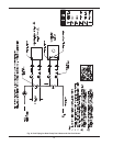
Fig. 3: Digital Water Temperature Control
7