


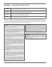
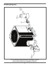
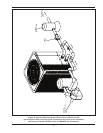

GAS
HEATER
AIR
FLOW
IN
AIR
FLOW
IN
AIR FLOW OUT
3 FT (90cm)
MIN
12” (30cm)
MIN
60” (1.5m)
M
IN
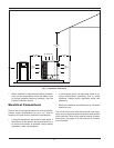
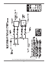
Fig. 1: Installation Clearances
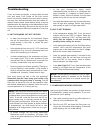
• When installed in areas where freezing tempera-
tures can be encountered, drain the water circuit
to prevent possible freeze-up damage. See the
Freeze Protection Section.
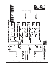
Electrical Connections
Refer to the unit rating plate below the control panel for
precise power requirements for your unit, and for
ampacity and over-current protection requirements.
• Locate the equipment disconnect means within 3
feet (90cm) of the heater’s electrical enclosure, or
as close to the heater as possible. Always satisfy
applicable codes and standards.
• In sizing power wiring, be especially aware of up-
sizing requirements necessary due to wiring
distances. Always satisfy applicable codes and
standards.
• Electrical installation should be done by a licensed
electrician only.
This unit is pre-wired to work with external control sys-
tems, heat-on-demand options and other external time
clock overrides. Refer to the external control system’s
instructions, and page 19 of this manual, for installa-
tion information.
6