


3
110497
Remove
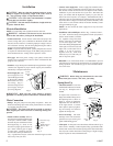
Fig. 7
45°
15°
Entering
Air
Leaving Air
Fig. 6
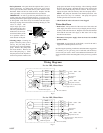
Black
White
Green
Green
Blue
White w/ Stripe
Installation
Wiring Box
GFCI Receptacle
Unit Cabinet
Required Service Disconnect
In Sight Of Unit
120V - 60Hz - 1PH
Or 240V
Equipment
Ground
120V - 60Hz - 1PH
(Separate Circuit)
L1
N
L1
N
Fig. 8
Fan
Motor
Pumps
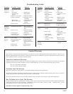
White
Black
Red
Green
Green
Blue
White w/ Stripe
Installation
Wiring Box
GFCI Receptacle
Unit Cabinet
Required Service Disconnect In
Sight Of Unit
240V - 60Hz - 3PH
Or 460V
Equipment
Ground
120V - 60Hz - 1PH
Separate Circuit
L1
L2
L3
L1
N
Fig. 9
Fan
Motor
Pumps
• Pad replacement. The pads should be replaced after 5 years or
before if necessary. To change pads, remove top access panel,
remove grill, and disconnect water delivery tube. Remove water
distributor holder and lift out media sections. Replace with the
same type media. You can purchase them from your dealer.
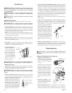
IMPORTANT: In order to get the best performance from your
cooling pads, they must be installed properly. If you have pur-
chased a pad with two equal angles, the following instructions can
be disregarded. Pads must always be installed with the steeper
flute angle sloping down towards the air entering side (Fig. 6). The
reason is simple. The
steeper angle puts more
water on the hot, dry, dirty
side of the pad where it is
needed most. It also coun-
teracts the tendency of the
air to push the water to-
ward the back of the pad.
• Cleaning pumps. Cleaning the
pumps is necessary once a year at
start-up. For your safety, discon-
nect from power source and unplug
pump. Remove the pump from
the mount bracket. Remove the
base of the pump (Fig. 7). Clean
the pump and turn the impeller to
ensure free operation. Remove the
pump spout and check for any blockage. After cleaning, reinstall
the base onto the pump. Reattach the pump to the mount in the
cooler to ensure that the pump will not overturn. Do not forget to
replace the spout and water delivery tube onto the pump outlet.
NOTE: The pump has automatic reset thermal protection. The
pump motor will stop if it overheats. The pump will operate
normal again after obstruction is cleared.
• Check bleed-off valve to be sure it is not clogged.
Winter Shut Down
• Drain water. Always drain all of the water out of the cooler and
water supply line when not in use for prolonged periods, and par-
ticularly at the end of the season. Keep the water line disconnected
from both the unit and water supply so that water will not seep
into the line and freeze.
• Disconnect from power supply when not in use for extended
periods of time.
• Cover unit. To protect the life of the finish, a cover for the unit is
suggested in extended periods of non use.
By following the operating, installation, and maintenance suggestions
as outlined, you can get many years of efficient and satisfactory
service from your cooler. In the event additional information is de-
sired, your dealer will be more than glad to assist you in every possible
way.
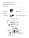
Wiring Diagrams
For 1 or 2 HP, 3 Phase Motor
For 1 or 2 HP, 1 Phase Motor