


7
INSTALLATION
ELECTRICAL CONNECTIONS
The wiring must comply with local codes. If you are not familiar
with the codes or wiring practices, get professional help.
Use only an Essick ECR-5 or ECR-7 wall mounted switch. This
new cooler does not require prewetting the pads before starting
cooling and does not have a pump.
Existing switches with
“pump only” position are not usable.
WARNING: TO REDUCE THE RISK OF FIRE OR ELEC-
TRIC SHOCK, DO NOT USE THIS FAN WITH ANY SOLID
STATE SPEED CONTROL DEVICE.
CAUTION: SHUT OFF THE ELECTRIC POWER AT THE
FUSE BOX BEFORE BEGINNING THE WIRING.
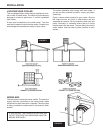
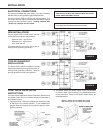
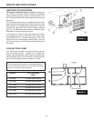
NEW INSTALLATIONS
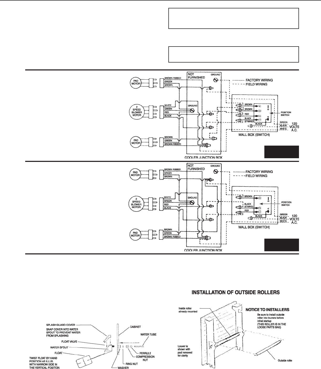
Use the Essick ECR-7 switch which has four
cooling positions and two vent positions:
Maximum Cool - high and low
Minimum Cool - high and low
Vent - high and low
This switch requires six wires to the cooler (in-
cluding cooler grounding conductor).
COOLER CHANGEOUT
INSTALLATIONS
The Essick ECR-5 switch is suitable for existing
installations where five wires go to the cooler (in-
cluding cooler grounding conductor). There are
two cool positions and two vent positions.
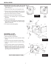
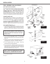
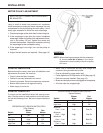
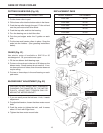
FLOAT VALVE INSTALLATION
INSTRUCTIONS
It is of the Utmost Importance that the Float Valve, Splash Guard
and Splash Guard Cover be installed exactly as described in
the illustration below.
1. The Float Valve - Must be installed with the narrow side
of the float in the vertical position. If not installed this
way the float will hang up and cause the reservoir drain
pipes to overflow.
2. The Water Spout and Water Spout Cover are provided
to prevent water from “spurting” and splashing outside
of the reservoirs. Snap in the Splash Guard Cover as
illustrated below.
FIGURE 8
FIGURE 9