


110526 3
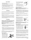
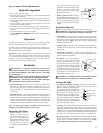
keep fl oat from turning. Place nut
(4) and ferrule (3) on water supply
line. Connect to fl oat fi tting and
tighten until water tight. Turn on
water supply and check for leaks.
Loosen screw (6) and adjust rod
(7) until water level is within 1” of
top of reservoir. Tighten screw (6).
Slide fl oat shield (8) over fl oat body
(5) until it snaps into place.
• Bleed-Off. Use of the bleed-off kit is recommended to prevent scale
build up by bleeding off small amounts of circulating water during
operation. Do not add any type of water treatment chemicals to the
water since they may damage the evaporative media.
Pulley And Belt Adjustments
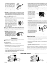
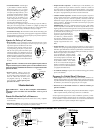
• Pulley adjustment. With an ammeter, check the motor amperage.
Adjust the pulley until the amperage draw on the motor is just below
that specifi ed on the motor nameplate. To
adjust the pulley, loosen the adjustment
set screw and rotate the sheave. Tighten
the set screw so that it is over a fl at area,
otherwise thread damage will occur. To
increase amperage draw, increase pulley
diameter. To decrease amperage draw,
decrease pulley diameter (see Fig. 6).
Recheck belt alignment.
CAUTION: Always check the amperage of the motor after ad-
justing pulley to be certain it does not exceed the amperage stamped
on the motor specifi cation plate. Improper pulley adjustment will
overload and burn out the motor.
• Belt tension. Loosen the motor mount
bolts and slide the motor back until the
belt is properly tensioned. A 3 lb. force
should defl ect the belt 3/4 inches (see
Fig. 7). Retighten motor mount bolts.
Do not adjust pulley to tighten belt.
Maintenance
WARNING: Before doing any maintenance be sure to disconnect
from power source. This is for your safety.
Spring Start-Up
• Belt tension. Check belt tension and readjust if needed.
• Grease bearings. The blower bearings in this unit should be greased
once a year with a good grade of ball bearing grease.
• Cleaning pads. A clean pad is more absorbent, effi cient and will give
more cool air. Annually, or when required, using a garden hose with
nozzle, back wash to clean out the openings, then clean off the inlet
face any scale or other obstruction to the passages. Slight scraping
may be required to remove hardened scale.
• Pad replacement. The pads should be replaced after 5 years or if
necessary. To change pads, remove top access panel, remove grill,
and disconnect water delivery tube. Remove water distributor holder
and lift out media sections. Replace with the same type media. You
can purchase them from your dealer.
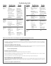
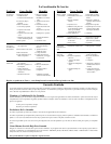
IMPORTANT: In order to get the best performance from your cool-
ing pads, they must be installed properly. If you have purchased a pad
with two equal angles, the following instructions can be disregarded.
Pads must always be installed with the steeper fl ute angle sloping
down towards the air enter-
ing side (Fig. 8). The rea-
son is simple. The steeper
angle puts more water on
the hot, dry, dirty side of
the pad where it is needed
most. It also counteracts
the tendency of the air to
push the water toward the
back of the pad.
• Cleaning pump. Cleaning the pump is necessary once a year at start-
up. For your safety, disconnect from power source and unplug pump.
Remove the pump from the mount bracket. Remove the base of the
pump (Fig. 9). Clean the pump and turn the impeller to ensure free
operation. Remove the pump spout and check for any blockage. After
cleaning, reinstall the base onto
the pump. Reattach the pump to
the mount in the cooler to ensure
that the pump will not overturn.
Do not forget to replace the spout
and water delivery tube onto the
pump outlet. The pump has au-
tomatic reset thermal protection.
Pump will operate normal again
after obstruction is cleared.
• Bleed off. Check bleed-off valve to be sure it is not clogged.
Winter Shut Down
• Drain water. Always drain all of the water out of the cooler and water
supply line when not in use for prolonged periods, and particularly at
the end of the season. Keep the water line disconnected from both
the unit and water supply so that it does not freeze.
• Disconnect from power supply when not in use for extended
periods of time.
• Cover unit. To protect the life of the fi nish, a cover for the unit is
suggested in extended periods of non use.
By following the operating, installation, and maintenance suggestions
as outlined, you can get many years of effi cient and satisfactory service
from your cooler. In the event additional information is desired, your
dealer will be more than glad to assist you in every possible way.
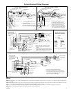
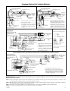
Ground
Blue/Black
White
Brown
=WireNut
Orange
Green
Green
Orange
Brown
White
Blue/Black
Pump
Com.
To
Switch
Com.
Pump
Blue/Black
White
Brown
Orange
Green
Green
Orange
=WireNut
Brown
White
Blue/Black
Ground
To
Switch
120 Volts 240 Volts
Pump Wiring Diagrams
Decrease
Amperage
Fig. 6
45°
15°
Entering
Air
Leaving Air
Fig. 8
Impeller
Remove
Base
Fig. 9
Fig. 7
3 Lb.
3/4 Inches
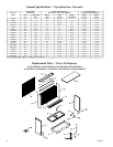
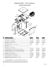
1
2
3
4
5
7
8
Fig. 5
6
9