


3
110498-2
will protect you from someone turning on
unit while you are working inside. This
should be done for your safety. Adjust
pulley to a larger diameter and readjust belt
tension, plug motor in, install inspection
panels, and retest amperage draw. Repeat
this process until correct amperage draw is
attained. Increasing motor pulley diameter
increases amperage draw. Decreasing motor pulley diameter decreases
amperage draw (see Fig. 9).
CAUTION: Do not operate cooler with larger amperage draw
than specifi ed on motor plate.
NOTE: No attempt should be made to completely install this unit
without the aid of an electrician or someone familiar with testing
amperage draw. Failure to comply with these instructions may void
your warranty.
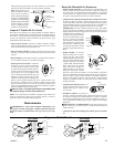
Bleed-Off
Installation of the bleed-off kit is recommended to increase the life of
the cooler. A bleed-off system is designed to prevent scale build up by
continually removing a small percent of the water in the pan.
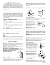
• Install Bleeder Tee and Tub-
ing. Refer to fi gure 8. Cut the
pump hose and insert the barbed
ends of the bleeder tee into each
cut end. Insert one end of the
bleeder tubing onto the bleeder
tee and run the other end out of
the cooler through the overfl ow
pipe. Note: A restrictor clamp is
provided which, if desired, may be installed onto the bleeder tubing
to restrict the amount of water being bleed off. The amount of water
to bleed off depends on the quality of the water in your area. Start
with 1-2 gal/hr and increase if needed.
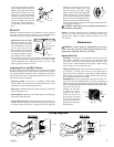
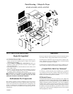
ASA35 only) and back post panel as
shown. Install washer (1) and nut (2).
Tighten to keep fl oat from turning.
Place nut (4) and ferrule (3) on water
supply line. Connect to fl oat fi tting
and tighten until water tight. Bend
rod (6) to adjust fl oat until water level
is about 1 inch below the top of the
overfl ow pipe. Slide fl oat shield (7)
over fl oat body (5) until it snaps into
place.
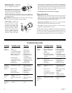
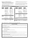
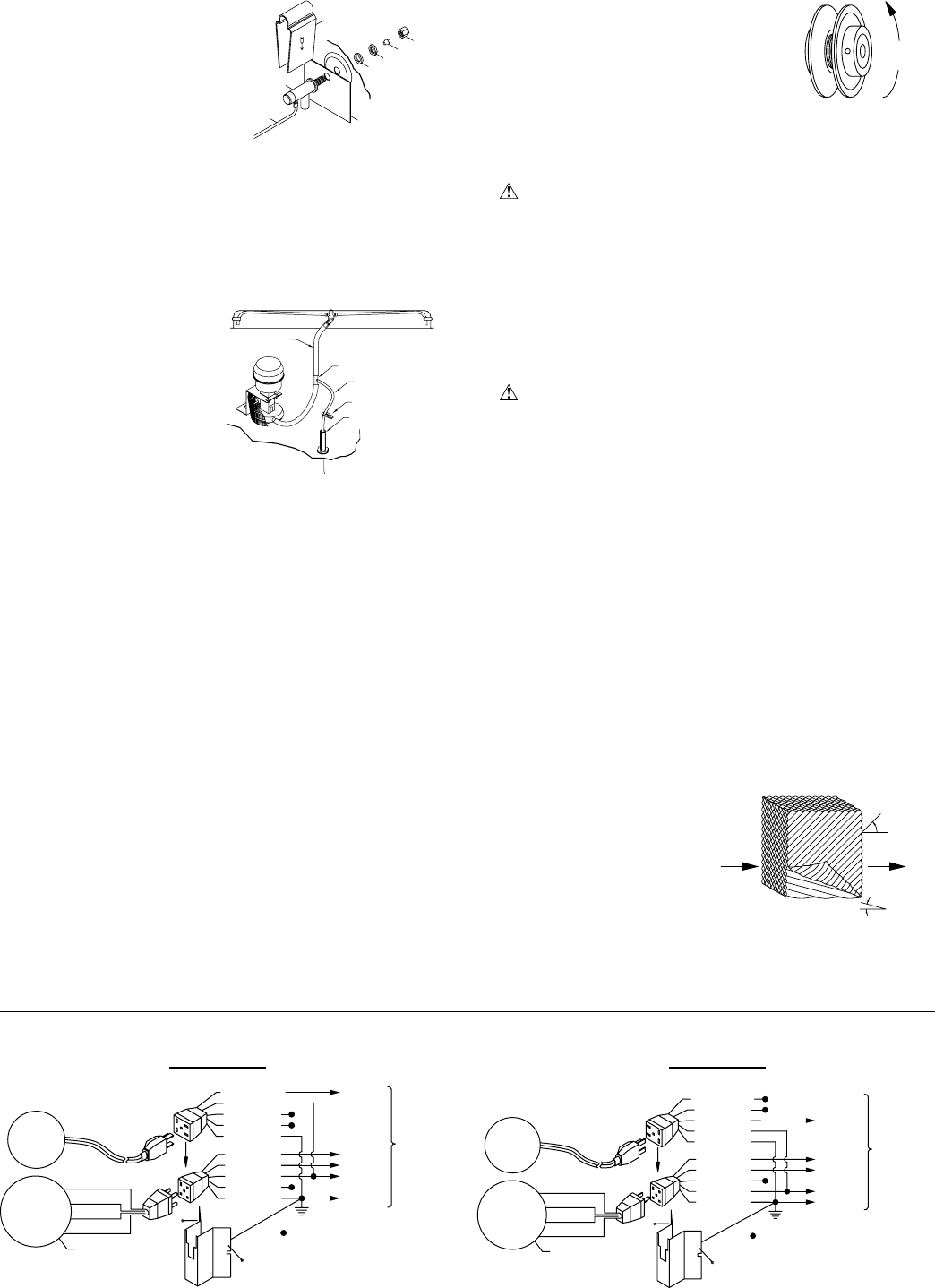
Com.
To Switch
Pump
Motor
Blower Motor
Red
Orange
Green
Black
Ground
Com.
Lo
Hi
= Wire Nut
Ground
Lo
Hi
Pump
Black
Red
White
Orange
Green
Green
Orange
Brown
White
Blue/Black
Blue/Black
White
Brown
Orange
Green
Green
Orange
White
Red
Black
Pump
Hi
Lo
Com.
Ground
= Wire Nut
Hi
Lo
Com.
Ground
Black
Green
White
Red
Blower Motor
Pump
Motor
To Switch
Maintenance
WARNING : Before doing any maintenance be sure power
is off. At the time you remove either inspection panel be sure to
unplug motor and pump. This is for your safety.
Spring Start-Up
• Clean pads. A clean pad is more absorbent, effi cient and will give
more cool air. Annually, or when required, using a garden hose with
nozzle, back wash to clean out the openings, then clean off the inlet
face any scale or other obstruction to the passages. Slight scraping
may be required to remove hardened scale.
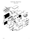
• Change pads if necessary. The pads should be replaced after 5 years
or if necessary. To change pads, remove top access panel, remove
grill, and disconnect water delivery tube. Remove water distributor
holder and lift out media sections. Replace with the same type media.
You can purchase them from your dealer.
IMPORTANT: In order to get the best performance from your cool-
ing pads, they must be installed properly. If you have purchased a pad
with two equal angles, the following instructions can be disregarded.
Pads must always be installed with the steeper fl ute angle sloping down
towards the air entering
side (Fig. 10). The reason
is simple. The steeper
angle puts more water on
the hot, dry, dirty side of
the pad where it is needed
most. It also counteracts
the tendency of the air to
push the water toward the
back of the pad.
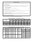
Amperage Draw And Belt Tension
This unit is equipped with an adjustable motor drive pulley for adjusting
the blower wheel speed to the proper loading on different duct systems.
It is important that the motor drive pulley is adjusted to correct size to
assure maximum air delivery without damage to the motor. Be sure to
follow these instructions carefully.
• Adjust drive pulley. After the unit is completely installed, adjust
the drive pulley to the least diameter and adjust belt tension. See the
maintenance section for adjusting belt tension.
• Start cooler. Install both inspection panels, start pump, and allow to
operate until pads are wet.
• Check amperage. With pads wet and unit started, check amperage
draw with an amperage meter.
• Adjust pulley if necessary. If amperage draw is less than motor rat-
ing, turn off electrical power and remove inspection panels (top pan
for models ADA35 and ASA35). Unplug motor inside cooler, this
45°
15°
Entering
Air
Leaving Air
Fig. 10
Wiring Diagrams
120 Volts 240 Volts
Decrease
Amperage
Fig. 9
1
2
3
4
5
6
7
Fig. 7
8 (ADA/
ASA35)
Restrictor
Overfl ow
Bleeder Tubing
Bleeder Tee
Pump Hose
Fig. 8