


2
110498-2
Electrical Installation
WARNING: Disconnect all electrical service that will be used
for this unit before you begin the installation.
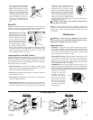
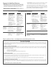
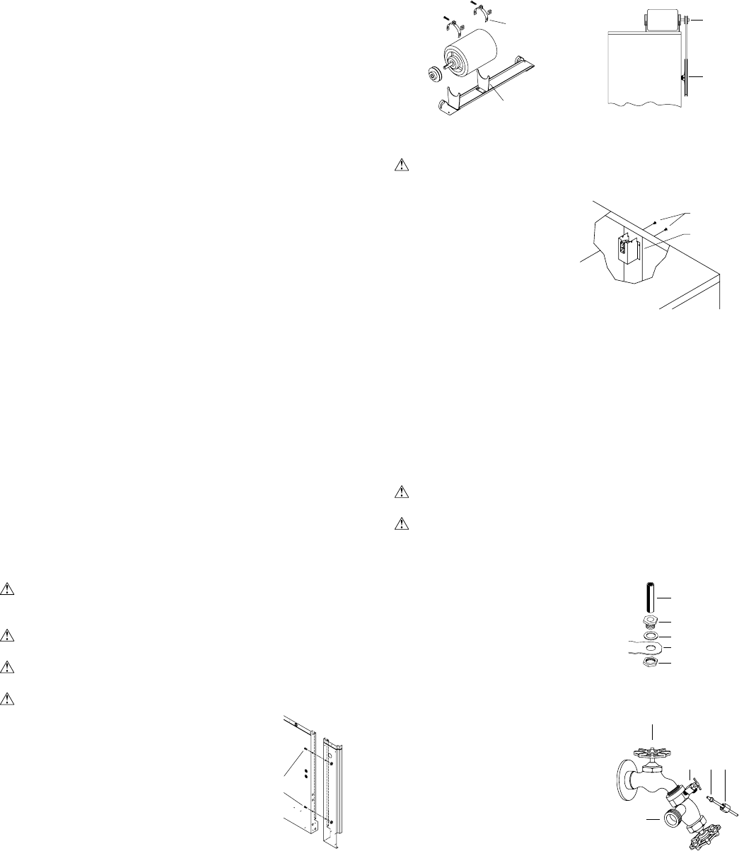
• Remove junction box. The elec-
trical junction box is located in
the upper inside of the left center
post. Remove the two screws and
pull box out from panel for access
to plug wiring (Fig. 4).
• Hook up electrical. Electrical
hook up should be done by a
qualifi ed electrician, so that all electrical wiring will conform to your
local standards. This unit is suppled with a 120V pump. For 240V
pump operation, a 240V pump must be purchased. The fan and pump
receptacles will support both 120V and 240V installations. See the
wiring diagrams for 120V and 240V installations on the following
page.
IMPORTANT: When a single speed motor is used, do not use the
red lead on the receptacle and motor plug wiring. Tape off end of
both of the red leads.
CAUTION: Pump receptacle is for grounded evaporative cooler
pump only. Do not plug anything else into receptacle.
WARNING: Make sure that cooler cabinet is properly grounded
to a suitable ground connection for maximum safety.
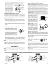
• Mount motor. Install blower motor in the motor mount yokes, adjust-
ing the yoke if necessary. Fasten with the provided mounting clips
(see Fig. 2). NOTE: Adjustable yoke will have to be reversed for 1
H.P. motors.
• Install pulley. Install the adjustable motor pulley so that it aligns
with the blower drive pulley (see Fig. 3) and tighten set screw.
Cooler Installation
CAUTION: Make sure that the mounting surface is strong
enough to support the operating weight of the cooler when in use.
(For operating weight, see Specifi cation Table.)
CAUTION: Never plug in cooler until installation is complete
and unit has been tested for rigidity.
CAUTION: Do not screw or drill within 5 inches of the bottom
of the wet module. You could puncture the reservoir.
CAUTION: If the unit is supported with legs at each corner,
the middle of the unit where the two sections
join must be supported as well.
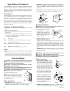
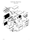
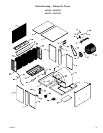
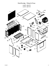
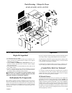
NOTE: You can separate the wet module
from the blower module by removing the 4
bolts (2 bolts in ADA35 and ASA35) from the
wet module side (Fig. 1)
Motor Installation
• Install motor cord. For typical 120V
installation, connect motor cord to motor using the following color
code: Black - Hi, Red - Low, White - Com., Green - Ground.
Wet
Module
Fig. 1
Mounting
Bolts
Open Windows To Exhaust Air
An often misunderstood concept of evaporative cooling is the amount
of air that should be exhausted. How much should you open your
windows? The fact is that most people do not open their windows
enough. The following two methods will help you determine the amount
to open your windows.
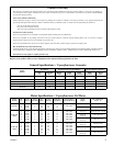
First Method
You should allow an opening of at least 2 square feet (288 square inches)
for each 1000 CFM rating of your unit. Example: At 3320 CFM,
model ADA 51 (1/2 hp) requires 6.6 square feet (950 square inches)
of opening (3320/1000 * 2 = 6.6). Multiply the number of windows
by window width in inches and divide this into the number of square
inches required for your size unit. This will give you the height to
open windows. In this example, four 36 inch wide windows should be
opened 6.6 inches each.
Champion Air Balancing Method
1. Take a piece of tissue paper and cut it lengthwise into 3 equal
strips.
2. Turn your cooler on high cool.
3. Open one window at least six inches wide in each room that you
want to cool.
4. Take the piece of tissue paper and put it up against the screen of the
open window furthest from the cooler discharge opening. Let go of
it. It will do one of three things.
IF It falls down.
THEN CLOSE all of the windows one inch and try step 4 again.
IF It plasters itself to the screen.
THEN OPEN all of the windows one inch and try step 4 again.
IF It stays on the screen lightly.
THEN PERFECT. You are done. Enjoy your cooler.
NOTES:
• When switching to low cool, you must rebalance your home. Repeat
step 4.
• Once you balance your home you can cool some areas more than others
by opening those windows more and closing the others by the same
amount. Repeat step 4 to make sure your home is still air balanced.
Screws
Fig. 4
Junction
Box
Water Connection
• Install overflow assembly. Remove
nut and place nipple through the hole in
the pan, with the rubber washer between
the pan and the head of the drain nipple
(Fig. 5). Screw on nut and draw up
tight against bottom of pan. Insert over-
fl ow pipe in nipple to retain water. The
overfl ow pipe may be removed to drain
pan when necessary. A garden hose
may be screwed on the drain nipple
to drain water away from your unit.
• Connect water supply line. Install
a sillcock and water valve on faucet
as shown by fi gure 6. Place the nut
and ferrule on the tubing and tighten
the nut until water tight. NOTE: Do
not connect the water supply to any
soft water applications.
• Install fl oat valve and fi ll pan. Refer to Fig. 7. Remove items 1, 2,
3, and 4. Insert fl oat body (5) through hole in splash plate (8) (ADA/
Faucet
Water Supply
Valve
Sillcock
Ferrule
Nut
Fig. 6
Rubber Washer
Overfl ow Pipe
Nipple
Bottom Pan
Nut
Fig. 5
Motor
Clips
Adjustable
Yoke
Fig. 2
Blower
Housing
Motor
Pulley
Blower
Pulley
Fig. 3