


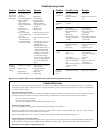

3
110498-3
During automatic operation, the control performs a 90 second water
dump cycle every 8 or 12 hours of pump operation. This interval can
be toggled between 8 or 12 hours by simultaneously holding the ‘Cool’
and ‘Fan’ buttons for 5 seconds. The selected interval is displayed for
a short time. This action also starts a manual dump cycle.
Ventilation Operation (Fan Mode)
The fan speed is set by the user, the water pump is turned off.
This mode is activated by pressing the ‘Fan’ button. A green LED
is illuminated, and the LCD indicates fan speed. Pressing the ‘Fan’
button again deselects this mode.
Pressing the ‘Up’ button selects maximum Fan speed, and ‘Hi’ is
displayed in the LCD; pressing the ‘Down’ button selects minimum
Fan speed, and ‘Lo’ is displayed in the LCD.
Time Delay Operation (Timer Mode)
Delayed start or fi nish in ‘Cool’ or ‘Fan’ mode.
The ‘Timer’ button is used to set a delay period of 2, 4 or 8 hours,
depending on how many times the button is pressed.
If the cooler is operating in ‘Cool’ or ‘Fan’ modes when the ‘Timer’
button is pressed, the delay period determines when the cooler will
switch off. If the cooler is Off when the ‘Timer’ button is pressed,
the delay period determines when the cooler switches on.
The starting mode is indicated by a fl ashing LED. You can change
this mode by pressing the appropriate button (‘Cool’ or ‘Fan’).
You can cancel the Timer function at any time by pressing the ‘Timer’
button until all the timer LED’s go out.
In The Event Of A Power Outage
If the cooler is operating in ‘Cool’ or ‘Fan’ mode when power is
interrupted, the cooler will resume in the same mode of operation
when the power is restored.
If the cooler was in any ‘Timer’ mode at the time of a power
interruption, the cooler will remain off when power is restored.
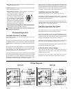
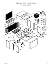
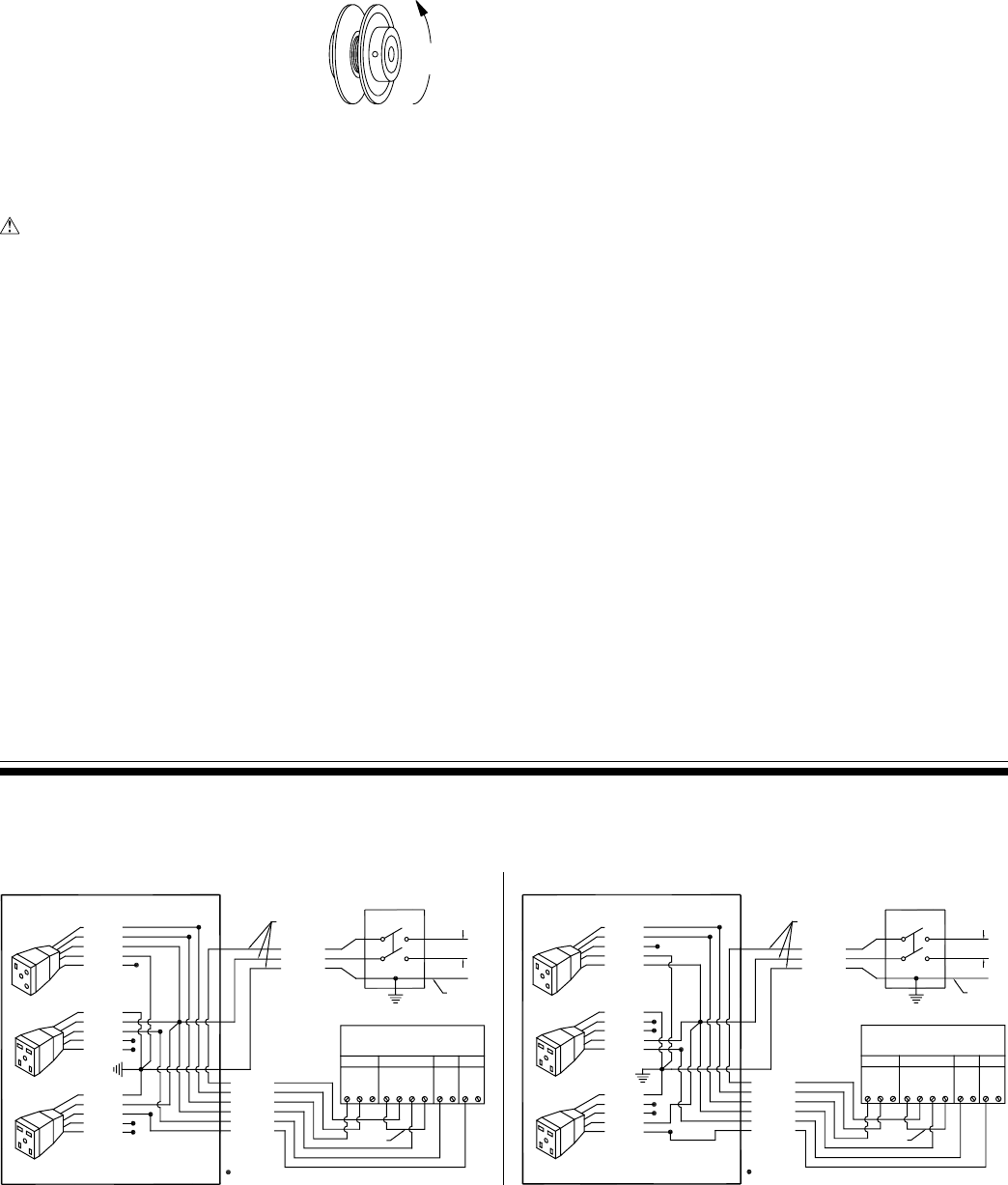
Wiring Diagrams
Thermostat Operation
Automatic Operation (Cool Mode)
The fan and water pump are controlled automatically to achieve the
desired comfort level.
This mode is activated by pressing the ‘Cool’ button. A blue LED
is illuminated, and for a few seconds the LCD will display the
‘Set’ temperature. Pressing the ‘Cool’ button again deactivates this
mode.
The Set temperature (the target temperature for control) may be altered
by repeatedly pressing or holding the ‘Up’ and ‘Down’ buttons. The
LCD will display ‘Set’ rather than ‘Room’ temperature for a short
time after pressing the ‘Up’ or ‘Down’ button.
On starting, if the pads in the cooler are too dry, the fan may be delayed
from starting until the pads have absorbed some water. This is called
Pre-wet and lasts for 2 minutes, indicated by a fl ashing blue LED.
Selecting ‘Fan’ and then ‘Cool’ will bypass the pre-wet and cause the
fan and pump to start immediately. (If cooling is required).
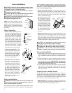
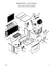
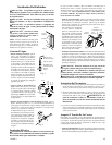
• Start cooler. Install both inspection panels, start pump, and allow
to operate until pads are wet.
• Check amperage. With pads wet and unit started, check amperage
draw with an amperage meter.
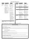
• Adjust pulley if necessary. If amperage draw is less than mo-
tor rating, turn off electrical power and
remove inspection panels. Unplug mo-
tor inside cooler, this will protect you
from someone turning on unit while
you are working inside. This should be
done for your safety. Adjust pulley to a
larger diameter and readjust belt tension,
plug motor in, install inspection panels,
and retest amperage draw. Repeat this
process until correct amperage draw is attained. Increasing motor
pulley diameter increases amperage draw. Decreasing motor pulley
diameter decreases amperage draw (see Fig. 6).
CAUTION: Do not operate cooler with larger amperage draw
than specifi ed on motor plate.
120 Volt 240 Volt
Decrease
Amperage
Fig. 6
FAN MOTOR
THERMOSTAT
RECEPTACLE
RECEPTACLE
CIRCULATINGPUMP
RECEPTACLE
DRAINPUMP
120VAC
WHITE
RED
COOLERTERMINALBOX
WHITE
GREEN
BLACK
GREEN
WHITE
BLUE
=WIRENUT
SWITCHLEADS
VIOLET
BLUE
YELLOW
GRAY
BLACK
RED
GREEN
WHITE
GRAY
GROUND
TOGGLESWITCH
(11)
FLo
FHi
FCom
LINK
L1
N
NLink
PP
PCom
DP
DCom
DUMPPUMPFAN PWR.SUPPLY
ORANGE
ORANGE
BROWN
BROWN
ORANGE
BLUE
WHITE
GREEN
SWITCHLEADS
=WIRENUT
WHITE
GREEN
BLACK
GREEN
WHITE
COOLERTERMINALBOX
RED
BLUE
GREEN
WHITE
BLUE
ORANGE
BROWN
BROWN
ORANGE
ORANGE
WHITE
240VAC
DRAINPUMP
RECEPTACLE
CIRCULATINGPUMP
RECEPTACLE
RECEPTACLE
THERMOSTAT
FANMOTOR
PWR.SUPPLYFAN
PUMP DUMP
DCom
DP
PCom
PP
NLink
N
L1
LINK
FCom
FHi
FLo
(11)
TOGGLESWITCH
GROUND
GRAY
WHITE
GREEN
RED
BLACK
GRAY
YELLOW
BLUE
VIOLET