


2
110498-3
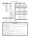
Cooler Installation
CAUTION: Make sure that the mounting surface is strong
enough to support the operating weight of the cooler when in use.
(For operating weight, see Specifi cation Table.)
CAUTION: Never start cooler until installation is complete
and unit has been tested for rigidity.
CAUTION: Do not screw or drill within 5 inches of the bottom
of the wet module. You could puncture the reservoir.
CAUTION: If the unit is supported with legs at each corner,
the middle of the unit where the two sec-
tions join must be supported as well.
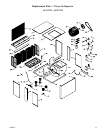
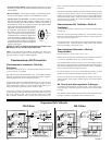
NOTE: For ease of installation you can
separate the wet module from the blower
module by removing the 4 bolts from the wet
module side (Fig. 1). Remember to unplug
the pump and drain pump before separating
the modules.
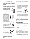
Water Connection
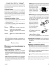
• Install overfl ow assembly. Remove
nut and place nipple through the hole
in the pan, with the rubber washer be-
tween the pan and the head of the drain
nipple (Fig. 2). Screw on nut and draw
up tight against bottom of pan. Insert
overfl ow into nipple to retain water.
The overfl ow pipe comes from the fac-
tory connected to the dump pump hose.
The overfl ow pipe may be removed to
drain pan when necessary. A garden
hose may be screwed on the drain nipple
to drain water away from your unit.
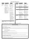
• Connect water supply line. Install
a sillcock and water valve on faucet
as shown by fi gure 3. Place the nut
and ferrule on the tubing and tighten
the nut until water tight. NOTE:
Do not connect the water supply to
any soft water applications.
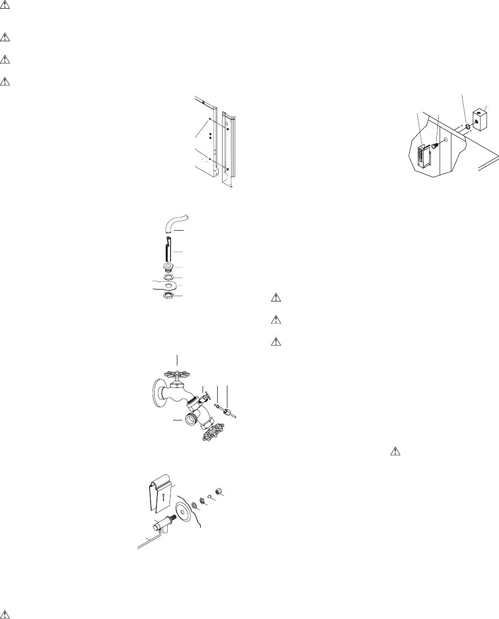
• Install fl oat valve and fi ll pan.
Refer to Fig. 4. Remove items 1,
2, 3, and 4. Insert fl oat body (5)
through hole in back post panel as
shown. Install washer (1) and nut
(2). Tighten to keep fl oat from turn-
ing. Place nut (4) and ferrule (3) on
water supply line. Connect to fl oat
fi tting and tighten until water tight.
Bend rod (6) to adjust fl oat until
water level is about 1 inch below
the top of the overfl ow pipe. Slide
fl oat shield (7) over fl oat body (5)
until it snaps into place.
should be adequately protected against overloads and short circuits.
Note: Electrical installation should be performed by a qualifi ed
electrician. Be sure to follow all National and Local Electrical
Codes when installing this cooler.
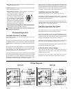
• Install weatherproof switch box. Located inside the unit in a
plastic bag is a switch box and cover, a chase nipple, a seal ring
and a toggle switch. Remove the electrical junction box (Fig. 5)
which is mounted on the inside of the center panel. From inside
the unit, insert the chase nipple
through the electrical access
hole. Slide the seal ring over
the chase nipple. Mount the
switch box to the outside of the
unit by threading the chase nip-
ple into the switch box. Run
the three switch leads through
the nipple and into the switch
box and reinstall the junction
box. Connect the green ground
lead to the ground screw in the
switch box.
• Supply power to unit. Run power to the external switch box and
connect to the two poles of the toggle switch. Connect the gray and
white leads from the cooler electrical box to the two poles of the
toggle switch. Refer to the appropriate wiring diagram to complete
the electrical installation of your cooler. Secure the switch into the
switch box and install the gasket and switch cover.
CAUTION: All openings in the external switch box must be
sealed to prevent water from entering the switch box.
CAUTION: Pump receptacles are for grounded evaporative
cooler pumps only. Do not plug anything else into receptacle.
WARNING: Make sure that cooler cabinet is properly
grounded to a suitable ground connection for maximum safety.
Thermostat Installation
1) Find a suitable location for the wall thermostat (away from sources
of heat, sunlight, or ventilation, and between 4 and 6 feet from the
fl oor). The thermostat may be mounted to a standard electrical
box.
2) Route an insulated four-conductor thermostat cable (or similar)
from the Control Box inside the cooler to the thermostat electrical
box. This cable is not supplied.
WARNING: The thermostat
cable should not be routed next to or enter the cabinet through
the same inlet as the power supply wire.
3) Connect the thermostat wires to the terminals on the back of the
wall control and to the terminals located on the left side of the
control box in the unit. Make sure to follow the color code found
next to each terminal.
Electrical Installation
WARNING: Disconnect all electrical service that will be used
for this unit before you begin the installation and leave it discon-
nected until the installation is complete.
The control box is factory wired and installed for either 120V or 230V
operation depending on the model you purchased. The supply power
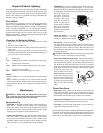
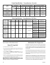
Amperage Draw And Belt Tension
This unit is equipped with an adjustable motor drive sheave for
adjusting the blower wheel speed to the proper loading on different
duct systems. It is important that the motor drive pulley is adjusted
to correct size to assure maximum air delivery without damage to the
motor. Be sure to follow these instructions carefully.
• Adjust drive pulley. After the unit is completely installed, adjust
the drive pulley to the least diameter and adjust belt tension. See
the maintenance section for adjusting belt tension.
Wet
Module
Fig. 1
Mounting
Bolts
Faucet
Water Supply
Valve
Sillcock
Ferrule
Nut
Fig. 3
1
2
3
4
5
6
7
Fig. 4
Rubber Washer
Overfl ow Pipe
Nipple
Bottom Pan
Nut
Fig. 2
Drain Pump
Hose
Fig. 5
Electrical
Box
Seal Ring
Junction
Box
Chase
Nipple