


3
110503-1
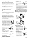
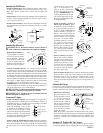
• Install fl oat and attach water line to
fl oat. The fl oat may be installed in either
the corner post or bracket (see Fig. 9). If
you have model 3000DD/N31D then the
fl oat should be mounted to the bracket.
Refer to fi gure 10 for installation instruc-
tions. Insert the fl oat (1) thru the hole
in the corner post or bracket. Install the
washer (2) and nut (3). Tighten to keep
the fl oat from turning. Place the nut (5)
and ferrule (4) on the water supply line.
Connect to fl oat fi tting and tighten until
water tight.
• Fill pan. Allow water to fi ll to
within 1” of top of pan and adjust
fl oat to maintain this water level.
This can be accomplished by bend-
ing the fl oat rod.
• Level water troughs. Operate
pump until pads are saturated.
Check each trough to see if water
is evenly dispersed in the trough.
If they are not, loosen adjustment
bolts and level trough. Retighten
bolts. Check to see that all pads
are saturated with water and that
there are no dry spots or openings
in the pads.
Maintenance
WARNING: Before doing any maintenance be sure power is
off. At the time you remove a pad frame be sure to unplug motor
and pump. This is for your safety.
Spring Start-Up
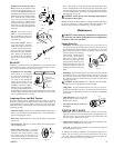
• Clean pump. Cleaning the pump is necessary once a year at start-up. For
your safety, turn unit off and unplug motor and pump. Remove the pump
from the mount slot. Remove the base of the pump (Fig. 13). Clean the
pump and turn the impeller to ensure free operation. Remove the pump
spout and check for any blockage.
After cleaning, reinstall the base
onto the pump. Press firmly to
make sure it is secure. Reattach
the pump to the mount in the cooler
using the plastic retainer to ensure
that the pump will not overturn. Do
not forget to replace the spout and
water delivery tube onto the pump
outlet.
• Oil bearings. The blower bearings and cooler motor in this unit should be
oiled with a few drops of non-detergent 20/30 weight oil once each year.
The motor does not need oil if it has no oil lines for oiling. Motors that
have no lines are lifetime oiled at the factory and require no further oiling
for the life of the unit.
CAUTION: Do not over oil. Over oiling can cause motor burn
out, due to excessive oil getting into motor winding.
• Change Pads. The pads should be replaced once or twice a season, de-
pending upon the length of the season. At the beginning and at mid season
a clean pad is more absorbent and effi cient and will deliver substantially
more cool air.
• Check belt tension. A 3 lb. force should
defl ect the belt 3/4 inches (see Fig. 14).
Readjust belt if needed.
• Check bleed-off valve to be sure it is
not clogged.
WINTER SHUT DOWN
• Drain water. Always drain all of the water out of the cooler and water
supply line when not in use for prolonged periods, and particularly at the
end of the season. Keep the water line disconnected from both the unit
and water supply so that it does not freeze.
• Unplug motor and pump. When cooler is not used for extended periods,
unplug the motor and pump from inside cooler.
• Cover unit. To protect the life of the fi nish, a cover for the unit is suggested
in extended periods of non use.
By following the operating, installation, and maintenance suggestions as
outlined, you can get many years of efficient and satisfactory service from
your cooler. In the event additional information is desired, your dealer will
be more than glad to assist you in every possible way.
Float
Corner
Post
Bracket
Fig. 9
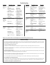
Amperage Draw And Belt Tension
This unit is equipped with an adjustable motor drive pulley for adjusting
the blower wheel speed to the proper loading on different duct systems. It
is important that the motor drive pulley is adjusted to correct size to assure
maximum air delivery without damage to the motor. Be sure to follow these
instructions carefully.
• Adjust drive pulley. After the unit is completely installed, adjust the drive
pulley to the least diameter and adjust belt tension. See the maintenance
section for adjusting belt tension.
• Start cooler. Install all pad frames, start pump, and allow to operate until
pads are wet.
• Check amperage. With pads wet and unit started, check amperage draw
with an amperage meter.
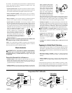
• Adjust pulley if necessary. If amperage
draw is less than motor rating, turn off elec-
trical power and remove pad frame. Unplug
motor inside cooler, this will protect you
from someone turning on unit while you are
working inside. This should be done for your
safety. Adjust pulley to a larger diameter and readjust belt tension, plug
motor in, install pad frame, and retest amperage draw. Repeat this process
until correct amperage draw is attained. Increasing motor pulley diameter
increases amperage draw. Decreasing motor pulley diameter decreases
amperage draw (see Fig. 12).
CAUTION: Do not operate cooler with larger amperage draw
than specifi ed on motor plate.
NOTE: No attempt should be made to completely install this unit without
the aid of an electrician or someone familiar with testing amperage draw.
Failure to comply with these instructions may void your warranty.
Decrease
Amperage
Fig. 12
Fig. 10
1
2
3
5
6
4
Faucet
Water Supply
Valve
Sillcock
Ferrule
Nut
Fig. 8
Fig. 14
3 Lb.
3/4 Inches
Bleed-Off
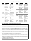
Installation of the bleed-off kit is recommended to increase the life of the
cooler. A bleed-off system is designed to prevent scale build up by continu-
ally removing a small percent of the water in the pan.
• Install Bleeder Tee and Tubing.
Refer to fi gure 11. Cut the pump
hose and insert the barbed ends
of the bleeder tee into each cut
end. Insert one end of the bleeder
tubing onto the bleeder tee and
run the other end out of the cooler
through the overfl ow pipe. Note: A
restrictor clamp is provided which,
if desired, may be installed onto the
bleeder tubing to restrict the amount of water being bleed off. The amount
of water to bleed off depends on the quality of the water in your area. Start
with 1-2 gal/hr and increase if needed.
Restrictor
Overfl ow
Bleeder Tubing
Bleeder Tee
Pump Hose
Fig. 11
Impeller
Remove
Base
Fig. 13