


2
110503-1
Installation
NOTE: The pump comes installed. The belt, motor pulley, and motor cord
and fl oat are included in the cabinet, the motor is shipped separately.
CAUTION: Make sure that the mounting surface is strong
enough to support the operating weight of the cooler when in use.
(For operating weight, see Specifi cation Table.)
CAUTION: Never plug in cooler until installation is complete
and unit has been tested for rigidity.
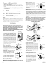
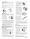
• Install Duct Adapters. If desired, a 4 piece duct
adapter is available as an optional accessory.
Call 1-800-643-8341 to obtain these from the
factory. Align the holes in the duct adapter to the
holes in the blower opening and attach using the
provided screws (see Fig. 1). Repeat for all four
sides. Note: All 4 pieces are identical except for
models 5000SD & N55/65S which have an offset
piece which attaches to the bottom of the outlet.
To install this offset piece, remove the screws
holding the cut-off plate and slide the offset duct
adapter between the blower opening and the cut-
off plate. You may need to loosen other screws
to do this. Line up the holes and secure with the
screws previously removed.
Motor Installation
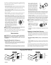
• Install motor cord. For typical 120V op-
eration, connect motor cord to motor using
the following color code: Black - Hi, Red
- Low, White - Com., Green - Ground. (See
Wiring Diagrams)
• Mount motor. Install blower motor in the
motor mount yokes, adjusting the yoke
if necessary. Fasten with the provided
mounting clips (see Fig. 2).
• Install pulley. Install the adjustable mo-
tor pulley so that it aligns with the blower
drive pulley (see Fig. 3) and tighten set
screw.
Electrical Installation
WARNING: Disconnect all electrical service that will be used
for this unit before you begin the installation.
Com.
To Switch
Pump
Motor
Blower Motor
Red
Orange
Green
Black
Ground
Com.
Lo
Hi
= Wire Nut
Ground
Lo
Hi
Pump
Black
Red
White
Orange
Green
Green
Orange
Brown
White
Blue/Black
Motor
Clips
Adjustable
Yoke
Fig. 2
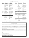
• Remove junction box. The elec-
trical junction box is located in the
upper inside corner of the cooler
cabinet. Remove the two screws
and remove the junction box (Fig.
4). Slide receptacles into slots in
junction box.
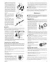
• Hook up electrical. Electrical hook up should be done by a qualifi ed
electrician, so that all electrical wiring will conform to your local standards.
This unit is suppled with a 120V pump. For 240V pump operation, a 240V
pump must be purchased. The fan and pump receptacles will support both
120V and 240V installations. See the wiring diagrams for 120V and 240V
installations. Note: Clip pump cord onto cord clip located on the bottom
of the junction box to keep cord our of the water.
IMPORTANT: When a single speed motor is used, do not use the red
lead on the receptacle and motor plug wiring. Tape off end of both of the
red leads.
CAUTION: Pump receptacle is for grounded evaporative
cooler pump only. Do not plug anything else into receptacle.
WARNING: Make sure the cooler cabinet is properly ground-
ed to a suitable ground connection for maximum safety.
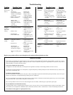
Water Connection
• Install overfl ow assembly. Place drain nipple
through the hole in the pan, with the rubber
washer between the pan and the head of the
drain nipple (Fig. 6). Screw on nut and draw
up tight against bottom of pan. Insert the
overfl ow pipe in the nipple to retain water.
The overfl ow pipe may be removed to drain
the pan when necessary. A garden hose may
be screwed on the drain nipple to drain water
away from your unit.
• Connect water supply line. Find the
closest supply of water. Use a saddle
valve (Fig. 7) to connect 1/4” tubing to
the cold water supply or use a Sillcock
and water valve connected to an out-
side faucet (Fig. 8). Place the nut and
ferrule on the tubing and tighten the
nut until water tight. IMPORTANT:
Do not connect the water supply to any
soft water applications. Soft water
will cause corrosion and decrease the
life of the cooler.
Wiring Diagrams
240 Volts
Fig. 5
120 Volts
Champion Air Balancing Method
1. Take a piece of tissue paper and cut it lengthwise into 3 equal strips.
2. Turn your cooler on high cool.
3. Open one window at least six inches wide in each room that you want
to cool.
4. Take the piece of tissue paper and put it up against the screen of the open
window furthest from the cooler discharge opening. Let go of it. It will
do one of three things.
IF It falls down.
THEN CLOSE all of the windows one inch and try step 4 again.
IF It plasters itself to the screen.
THEN OPEN all of the windows one inch and try step 4 again.
IF It stays on the screen lightly.
THEN PERFECT. You are done. Enjoy your cooler.
NOTES:
• When switching to low cool, you must rebalance your home. Repeat step
4.
• Once you balance your home you can cool some areas more than others by
opening those windows more and closing the others by the same amount.
Repeat step 4 to make sure your home is still air balanced.
Blue/Black
White
Brown
Orange
Green
Green
Orange
White
Red
Black
Pump
Hi
Lo
Com.
Ground
= Wire Nut
Hi
Lo
Com.
Ground
Black
Green
White
Red
Blower Motor
Pump
Motor
To Switch
Blower
Housing
Motor
Pulley
Blower
Pulley
Fig. 3
Rubber Washer
Overfl ow Pipe
Nipple
Bottom Pan
Nut
Fig. 6
Cold
Water
Pipe
Saddle
Valve
1/4” Tubing
Fig. 7
Fig. 1
Duct Adapter
Cut-Off Plate
Screws
Fig. 4
Junction Box
Clip