


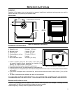

Initial Installation
QUALIFIED INSTALLERS ONLY
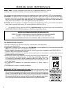
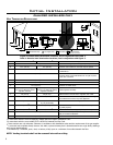
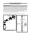
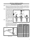
Vertical
Termination
Storm Collar
Flashing
Round Support
Box/Wall Thimble
Ceiling Firestop
Pipelength
Pipelength
Cathedral Ceiling
Support Box
Pipelength
Round Support
Box/Wall Thimble
Pipelength
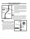
Horizontal
Termination
90° Elbow
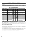
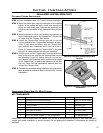
PLANNING YOUR INSTALLATION:
When planning your installation, it will be necessary to select the proper length of vent pipe for your particular
requirements. It is important to note when passing through a wall, the maximum allowable wall thickness is
10 inches (25.4 cm), 1 inches (3.8 cm) clearance to combustibles must be maintained. Select the amount of
vertical rise desired for “vertical-to-horizontal” type installations. To determine the length of vent pipe required for
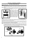
vertical installations, measure the distance from the appliance ue outlet to the ceiling, the ceiling thickness, the
vertical rise through the attic or second story, and allow for sufcient vent height above the roof line. For two story
applications, a re stop is required at each oor level. If an offset is needed in the attic, additional pipe and elbows
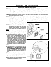
will be required. To connect the venting system to the appliance ue outlet, a twist-lock adapter is built into the
appliance at the factory. Refer to ‘Vent Conguration and Restrictor Settings’ for venting parameters.
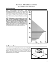
Your total vent pipe length must be within the shaded area of Figure 4. If a 90° elbow is used in the horizontal
plane, 36” (91.4 cm) must be subtracted from the allowable horizontal run.
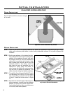
There are three (3) basic types of Direct Vent System installations. The two (2) types of installations are:
Figure 6: Common Horizontal Installation.
Figure 7: Common Vertical Installation.
9