


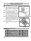
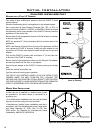

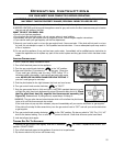

ADJUSTING THE VENTURIES:
• Remove the ash shelf by undoing the screw at each end, pull
shelf towards you.
• Remove one screw from the cover plate located below the
ash shelf. Loosen the other screw (do not remove) swing the
cover plate out of the way and tighten screw down to hold it in
place.
• With along screwdriver rotate spring clips to open or close the
shutter to the desired setting.
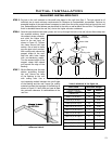
The venturies allows the amount of air coming into the replace to
be adjusted in order to accommodate different climates and venting
arrangements. Start the pilot and then the burner. Make sure the
pilot ame is burning normally and none of the burner ports are
plugged. Let the replace burn for roughly fteen minutes and
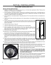
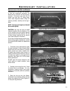
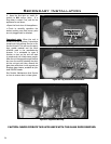
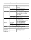
then examine the ames, compare the ames to Figure 37.
The ideal ame will be blue at the base and light orange above. The ames should be of medium height. If the
ames look like this, no venturi adjustment is needed. If the ames are fairly short and mostly blue, the replace
is getting too much air. Therefore, the venturies should be closed slightly until the correct ames are achieved.
Flames that are very orange, with tall, dark, stringy tips, are not getting enough air. Open the venturi until the
ames clean up. If the venturi is opened, or closed all the way, and the correct ames cannot be attained, turn off
the gas and contact the dealer.
Warning: Incorrect venturi adjustment may lead to improper combustion, which is a safety hazard. Contact the
dealer if there is any concern about the venturi adjustment.
Initial Installation
20
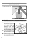
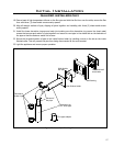
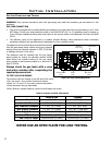
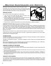
REPLACING THE BLOWER:
Figure 28: Blower (Fan) Removal.
1. Turn the unit off and remove the log set.
2. Remove the burner tray assembly by removing the
screw on either side of the tray, between the front and
rear burners. Lift the tray out.
3. Remove the four (4)
5
/16” bolts that hold the blower
mounting plate to the back rewall. Use a light
lubricating oil on screws before removal.
5. Carefully pull the blower assembly into the rebox
(see Figure 28). Install the blower onto the mounting
bracket (blower outlets pointing through the two holes
in the bracket) using the 4 screws provided.
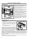
5. Connect wires according to the wiring diagram. If
removing the blower, disconnect the blower leads from
the harness. Remove the blower.
6. To re-install, check mounting plate gasket if damaged
replace with new one and reverse steps 1 through 4.
Refer to “Secondary Installation - Installation of Panel
Set” and “Secondary Installation - Installation of Log
Set and Embers”.
Figure 29: Blower (Fan) Removal.