


16
INSTALLATION INSTRUCTIONS:
1. Decide on a location for the unit that will meet any or all local code requirements. Refer “Planning Your
Installation” and “Clearances to Combustibles”.
2. Set the appliance in the desired location. Determine if any wall studs, electrical wiring, or plumbing pipes are
in the way of the venting system as it passes through the wall. If obstructions are found in the wall it may be
necessary to adjust the location of the appliance.
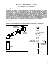
3. Set the appliance in the desired location. Temporarily place a 24” (61 cm) section with the non-crimped end on
the unit
4. Install the 90° elbow onto the vertical pipe on the stove pointing in the direction that the vent will exit the
structure.
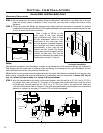
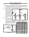
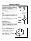
5. Project a level line from the center point of the elbow. Using this center point, scribe
a 10” (25.4 cm) hole or square on the wall. Cut the hole out on both the interior and
exterior wall surface.
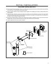
6. Frame the hole as shown in Figure 9.
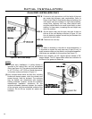
7. Install the wall thimble and secure the thimble to the inner wall surface.
8. With the appliance still in place install the 24” (61 cm) horizontal section on the
elbow and let this section of pipe protrude through the exterior surface. Mark the
pipe so that when it is cut it will be ush with the exterior wall.
9. Dismantle the outer pipe sections.
10. Remove the 4” (10 cm) ue collar from the unit and remove any loose sealant. Install
the new Ø 4” (10 cm) by 5” (12.5 cm) ue collar provided in this kit.
11. Stretch the liner out. Attach the exible liner to the vent termination cap by placing
a small bead of high temperature silicone on the vent termination and slide the ex
liner onto the vent terminal and secure with three (3) sheet metal screws evenly
spaced.
12. Dress the ex liner through the wall thimble and attach the vent terminal to the
outside of the house using four (4) wood screws provided. The use of non-hardening
mastic should be used around the vent to ensure a watertight seal.
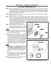
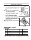
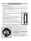
13. Install two (2) wire spacer around the ex pipe. Slide the horizontal section of pipe over the exible liner. Ensure
the wire spacers are positioned at either end of the pipe (refer to Figure 21 and 22).
14. Install the horizontal section of pipe through the wall thimble, ensure
that this portion of pipe slides onto the vent termination cap.
15. Slide the inside nished collar over the horizontal section of pipe and
secure to wall using the screw provided.
16. Slide the 90° elbow over the ex pipe. Do not slip the outer
sections of pipe together, you will require some movement
in these pipe section in order to secure the ex pipe to the
ue outlet on the appliance.
17. Stretch the ex liner to a length long enough to ensure the ex liner
can be easily connected to the ue outlet of the appliance.
18. Install the remaining wire spacers over the exible liner and install
the vertical section of pipe. Ensure the wire spacers are positioned
at either end of the pipe (refer to Figure 21 and 22).
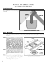
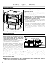
Initial Installation
QUALIFIED INSTALLERS ONLY
Figure 21: Cut away of
spacers on Flex Pipe.
Figure 22: Top view of spacers on Flex
Pipe.