


12
Initial Installation
QUALIFIED INSTALLERS ONLY
VERTICAL INSTALLATION:
STEP 1. Check the instructions for required clearances (air spaces) to combustibles when passing through ceilings,
walls, roofs, enclosures, attic rafters, or other nearby combustible surfaces. Do not pack air spaces with
insulation.
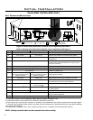
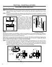
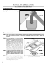
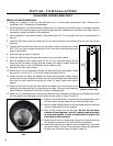
CORNER INSTALLATIONS:
Outside or
Inside Wall
Outside Wall
Figure 13: Corner installation top vented.
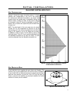
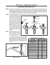
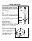
1
1
/
2
” (4cm)long
wood screw (x4)
10” (25.4cm) x10”(25.4cm)
inside framing
Ceiling Joist
Framing
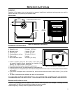
Figure 14: Wall Framing for 10” (25.4 cm) x 10” (25.4
cm) Hole for Vertical Installation.
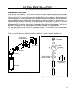
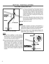
STEP 2. Set the gas appliance in the desired location.
Drop a plumb bob down from the ceiling to the
position of the appliance ue exit, and mark
the location where the vent will penetrate the
ceiling. Drill a small hole at this point. Next,
drop a plumb bob from the roof to the hole
previously drilled in the ceiling, mark the
spot where the vent will penetrate the roof.
Determine if ceiling joists, roof rafters, or
other framing will obstruct the venting system.
You may wish to relocate the appliance, or to
offset, to avoid cutting load bearing members.
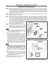
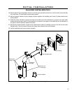
STEP 3. To install the Round Support Box/Wall Thimble
in a at ceiling, cut a 10 inch (25.4 cm) square
hole in the ceiling, centered in the hole drilled
in Step 2. Frame the hole as shown in Figure
14.
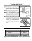
STEP 4. Assemble the desired lengths of black pipe and
elbows necessary to reach from the appliance
adapter up through the Round Support Box.
Insure that all pipe and elbow connections are
in their fully twist-locked position.
Do not interfere with the structural integrity
of the walls.