


11
Operating Instructions and Owner’s ManualEnerco | Compact Unit Heater
13. If appliance still will not operate, follow the instructions “TO
TURN
OFF GAS TO UNIT” and call your service technician or
gas
supplier.
TO TURN OFF GAS TO UNIT
1. Set thermostat to lowest level.
2. Turn off all electrical power to unit if service is to be
performed
.
3. Depress knob on gas valve; knob will snap to OFF.
HEATING SEQUENCE OF OPERATION
1. When the thermostat calls for heat, the combustion air
bl
ower starts immediately.
2. Combustion air pressure switch proves blower operation
be
fore allowing power to the ignition controller. This switch is
factory set and no adjustment is necessary.
3. After prepurge of approximately 30 seconds, the spark
ignition
is energized and the solenoid valves open in the gas
valve
.
4. The spark then ignites the gas, the ignition sensor proves the
flame
and the combustion process continues.
5. In the event that the flame is not detected after the first 10-
second
trial for ignition, the controller will repeat steps 3 and
4 an additional two times before locking out the gas valve.
Ignition
control will then automatically repeat steps 3, 4, and 5
after
60 minutes.
To interrupt the 60-minute lockout period, move thermostat
from “Heat” to “OFF” then back to “HEAT.” Heating
seq
uence then restarts at step 1.
6. The burners shall light without noticeable crossover delay.
There
shall be no flame lifting from the burner heads,
flashb
ack or burning within the burner. The flames shall be
predominantly
blue in color and shall be approximately
centered
in the tubes with no apparent impingement taking
place
.
7. The ignition control will energize the fan approximately 45
seconds
after ignition is established.
8. After the thermostat demand is satisfied the gas valve is
closed;
5 seconds after the demand is satisfied the
combustion
air blower is shut off.
9. The control center shall shut off the system fan approximately
150 seconds after the gas valve is denergized.
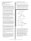
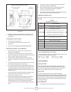
IGNITION CONTROL LED
The ignition control board contains a green LED which indicates the
following
:
TABLE 3
IGNITION CONTROL LED
GAS CONVERSION KIT OPTIONAL
ADJUSTMENTS
HIGH ALTITUDE
Units may be fired at full input up to 2000 ft. (610m) above sea
level. Above 2000 ft. (610m), manifold pressure must be adjusted
on
some units. Adjust pressure regulator to pressure shown in
table
4 for natural gas and table 5 for LP/propane gas.
GAS FLOW
To check for proper gas flow to the combustion chamber,
determine
the Btu input from the appliance rating plate. Divide this
input
rating by the Btu per cubic feet of available gas. Result is the
required number of cubic feet per hour. Determine the flow of gas
through
the gas meter for two minutes and multiply by 30 to get
the
hourly flow of gas.
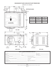
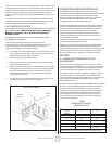
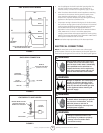
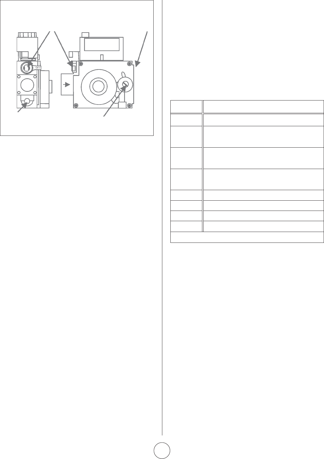
GAS PRESSURE
1. Check gas line pressure with unit firing at maximum rate. A
MANIFOLD
PRESSURE
TAP
INLET
PRESSURE TAP
ROBERTSHAW 2000DER GAS VALVE
GAS VALVE KNOB SHOWN
IN
OFF POSITION
MANIFOLD
PRESSURE ADJUSTMENT
SCREW
UNDER CAP
LED UNIT OPERATION
Slow Flash* Normal Operation - No call for heat
Fast Flash Normal Operation - Call for heat
Cur
rent signal at FLAME terminal 0.6 to 1.0 microamps
2 Flashes System lockout - failed to detect or sustain flame
Current
signal at FLAME terminal <0.6 microamps
3 Flashes Pressure switch failed closed before CAB is energized
or
failed open after CAB is energized
4 Flashes High limit or rollout switch open
5 Flashes Flame sensed and gas valve not energized
Steady
Off Loss of power
Steady On Ignition control failure
*When thermostat is placed in continuous fan mode LED will slowly flash.
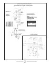
FIGURE 10
Can be purchased at any Enerco / Mr. Heater dealer or direct from
the factory under the following numbers
45NG--TO-- LP-----60067 75NG--TO-- LP-----60069
45LP---TO--NG-----60066 75LP---TO--NG-----60071