


19
Operating Instructions and Owner’s ManualEnerco | enerRadiant® XL Series Heater
Outside Combustion Air Supply
The Ener-Radiant XL heater is approved for installation with an
outside air supply system. Some compounds such as halogenated
hydrocarbons or other corrosive chemicals in the air can be drawn
into the equipment and cause an accelerated rate of corrosion
of some of the heater components. The use of such chemical
compounds near the enclosure should be avoided.
IMPORTANT: If the building has a slight negative pressure or
contaminants are present in the air, an outside combustion air supply
to the heaters is strongly recommended.
For an outside air supply, a four (4”) inch O.D. single wall pipe may
be attached to the heater. The duct may be up to forty-ve (45’) ft.
maximum length or two (2’) ft. minimum length with no more than
two (2) elbows. (See General Requirements in page 21 for additional
information.) An outside air supply should not be used with the draft
hood venting conguration.
The air supply duct may have to be insulated to prevent
condensation on the outer surface. The outside air terminal should
be securely fastened to the outside wall by drilling four (4) 1/4”
diameter holes in the outside ange; wood screws or bolts and
expansion sleeves may be used to fasten terminal.
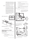
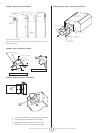
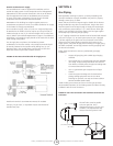
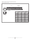
FIGURE 16: Non-Pressurized Outside Air Supply Duct
Outside Air Terminal: Use ACME #104 Enerco Stk. #19030.
PVC Pipe, “Dryer Hose”, or equivalent may be used instead of
standard vent pipe.
SECTION 6
Gas Piping
Read applicable warnings in (Section 1) before proceeding with
Gas Pipe installation. Improper installation may result in property
damage, severe injury, or death.
Meter and service must be large enough to handle all the burners
being installed plus any other connected load. The gas line which
feed the system must be large enough to supply the required gas
with a maximum pressure drop of 1/2” water column. When gas
piping is not included in the layout drawing, the local gas supplier
will usually help in planning the gas piping.
A 1/2” tapping at each burner location must be located and oriented
as shown in (Figure 17). To check system pressure, put a plugged
1/8” NPT tapping in the gas line at the connection to the burner
farthest from the supply. Before connecting the burners to the
supply system, verify that all high pressure testing of the gas piping
has been completed. Do not high pressure test the gas piping with
the burners connected.
Follow these instructions to ensure a professional gas supply
installation:
• Support all gas piping with suitable pipe hanging
materials.
• Use wrought iron or wrought steel pipe and malleable
iron tting. All pipe ttings should be new and free
from defects. Carefully ream the pipe and tubing ends
to remove obstructions and burrs.
• Use L.P. gas-resistant joint compound on all pipe
threads.
• Check the pipe and tubing ends for leaks before
placing heating equipment into service. When
checking for gas leaks, use soap and water solution:
NEVER USE AND OPEN FLAME.
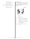
Install the ex gas connector as shown. The ex gas connector
accommodates expansion of the heating system and allows for easy
installation and service of the burner.
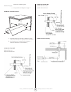
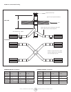
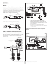
FIGURE 17: Gas Line Connection with Stainless Steel Flex Gas
Connector
Shut-Off Valve must be parallel
to burner gas inlet. The 2”
displacement shown is for the cold
condition. This displacement may
reduce when the system is red.
Shut – off Valve
12 "
2"
1/2" Stainless Steel Flex Gas Connector
Stk. #16401
90°
45°
0°
45°