


21
Operating Instructions and Owner’s ManualEnerco | enerRadiant® XL Series Heater
SECTION 7
Operation & Maintenance
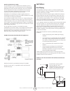
Sequence of Operation
1. Turn the thermostat up. When the thermostat calls for
heat, blower motor will energize.
2. When the motor approaches nominal running RPM,
the air proving switch closes and activates the ignition
module.
3. The ignition module then energizes the hot surface
igniter for a timed warm-up period (approximately 45
to 60 seconds.)
4. After the warm-up period, the gas valve is energized.
5. During the last part of the sequence, the igniter is de-
energized and is converted to a ame sensing rod.
6. If a ame is detected, the gas valve remains open.
When the call for heat is satised, and the system
control mechanism de-energizes the burner line
voltage supply, the gas valves are turned off.
7. If no ame is detected on a single-try module, the gas
valve is closed, and the module will lockout until it is
reset. Reset is accomplished by removing power from
the module for at least ve (5) seconds (thermostat
cycle required.)
8. If no ame is detected on a three-trial module, the
gas valve is closed, and a purge period begins. After
the purge, the module acts to power the igniter for a
second warm-up period, and a second trial for ignition
period. If ame is still not established, a third and
nal purge, warm-up, and trial cycle begins. After
three trials, the module will lockout until reset. Reset is
accomplished by removing power from the module for
at least ve (5) seconds (thermostat cycle required.)
9. On a three-trial module, if ame is established and
lost on the rst or second trial, the gas valve is turned
off, a purge, warm-up, and trial for ignition will occur
on a three-trial module, only three trials for ignition
are allowed per thermostat cycle.
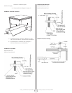
Maintenance
For best performance, the following maintenance procedures should
be performed before each heating season:
1. Be sure gas and electrical supply to heater are off
before performing any service or maintenance.
2. Check condition of blower scroll and motor. Dirt and
dust may be blown out with compressed air, or a
vacuum cleaner may be used.
3. Check condition of burner. Carefully remove any dust
or debris from inside the burner box or burner cup.
4. Inspect the igniter. Replace igniter if there is excessive
carbon residue, erosion, breakage or other defects.
5. Check the inside of the ring tube with a ashlight. If
carbon or scale are present, scrape out the deposits
with a wire brush or rod, or metal plate attached to a
wooden pole.
6. Check to see that the burner observation window is
clean and free of cracks or holes. Clean or replace as
necessary.
7. Check the ue pipe for soot or dirt. After cleaning as
necessary, re-attach the ue pipe to the heater.
8. Outside surfaces of heater may be cleaned by wiping
with a damp cloth.
9. A qualied service agency should be contacted for
service other than routine maintenance.
10. Check vent terminal and fresh air inlet to see that they
have not been blocked during the non-heating season.
If either pipe is restricted, the air switch won’t close,
resulting in a no-heat situation.
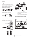
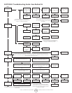
Troubleshooting
CAUTION: Before opening the Ener-Radiant XL
burner door for any type of service, be sure
the gas supply has been shut off at the heater
and the electrical cord from the burner box has
been unplugged.
Blower Motor 1. Is the thermostat calling for heat? Is there
Fails to Run: 115V at the burner receptacle?
2. Check blower side door for seal. Check door
switch. Replace if necessary/
3. Check blower for obstructions. Replace
blower if necessary.
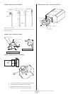
Igniter 1. Check igniter for damage. Replace if
Does Not Glow: necessary.
2. Check voltage and resistance at igniter.
(Voltage should be 115V. Resistance should be
40-75 ohms.)
3. Check for obstructions to the air inlet and
outlet.
4. Check wiring and hose connections to the
air switch. Replace if necessary.
5. Check voltages at transformer primary and
secondary. Replace transformer or module if
necessary.
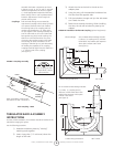
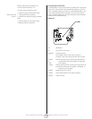
Valve Does Not Gas pressure downstream of gas control can
Come On: be measure by using a manometer and
connecting to pressure tap on control/
1. Check to see if manual valve heater is ON.
2. Check to see if manual valve knob on heater
gas control in ON.
3. Supply gas pressure can be checked at
1/8” NPT pressure tapping on heater external
manual valve.
4. Check to see if gas control is opening: no
manifold pressure indicates valve is closed.
If the valve is closed, either the gas valve or the
ignition module is faulty.
WARNING: Do not disconnect ground leads
inside heater. Do not interchange grounded
and ungrounded leads on transformer or
ignition module.
Burner Does Not 1. Check to see if gas lines were properly
Light: purged of air.
2. Check inlet and outlet gas pressure during
ignition period.
Natural inlet pressure should be 4.6”