


14
Enerco | enerRadiant® XL Series Heater Operating Instructions and Owner’s Manual
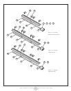
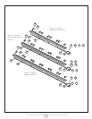
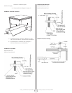
Assemble the heater components as shown
in Figures 2a, 2b, 2c, 2d, 2e, and 2f. Optional
reector congurations are shown in (Figure
1). Install appropriated suspension hardware,
beam clamps, chain or rod at predetermined
locations. Adjustment of chain length will
provide uniform pitch.
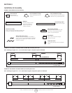
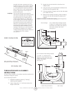
Couplings: Tube and tube ttings are connected by
wrap-around couplings which clamp by means
of a tapered, hammer-driven lock member.
The starting ends of the coupling and lock
member are identied by 1/4” holes which
are put together when starting assembly. Be
sure the tube ends are in line and tube ends
butt against stop pin(s) inside coupling. The
slide bar is to be hammer-driven to a point
of securing the coupling snugly to the tubes.
Over-driving will result in distortion of the
coupling or slide bar lip to a point decreasing
the holding the capability of the coupling.
Coupling should be tight when the slide bar is
+- 2” from the end of the coupling.
(See Figure 3)
Tighten
Loosen
Hole 1
Coupling
Assembly
Impact
Block
Hole 2
Tube
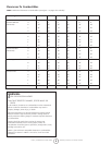
TURBULATOR BAFFLE ASSEMBLY
INSTRUCTIONS
For ease of eld installation, the turbulator should be installed in the
tube before hanging the system.
Use the following procedure:
1) Assemble turbulator pieces by “twisting”
matching ends together.
2) Insert a long wire (11 ft. minimum) down the
length of the tube.
FIGURE 3: Coupling Assembly
When assembling coupling note
the location of Hole 1 and Hole 2
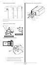
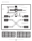
Plain Coupling - 14612
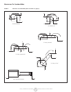
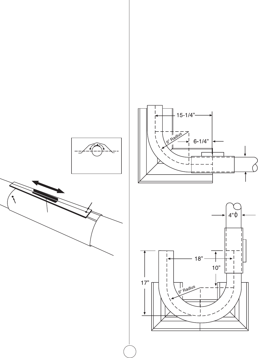
90° Elbow
Elbow Fitting Dimensions
U-Tube Fitting Dimensions 180° U-Tube
Orient coupling so that
the impact block is above
tube centerline.
3) Attach the wire to the hole in the tab on the
adapter piece.
4) Using the wire, pull the assembled turbulator into
the tube from the opposite side.
5) Pull the turbulator through until just the tab comes
out. Detach the wire.
6) Bend the tab around the tubing. When installing
the tube, the tab will be locked in place by the
adapter.
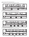
FIGURE 4: Installation of Elbow & Coupling (optional equipment)
Elbow Package: Stk. # F106415 Elbow Package includes:
(1) elbow, (1) coupling and (1) refelctor.
Install elbow into radiant tube sequence
where plans indicate a 90° bend
(see Figure 4).
Stk. # F106414 U-Tube Package includes:
(1) U-tube, (1) coupling and (2)
reectors. Install U-tube elbow into
radiant tube sequence where plans
indicate a 180° bend
(see Figure 4).