


26670-0-0110 Page 25
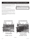
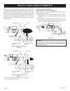
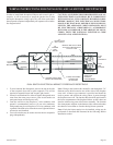
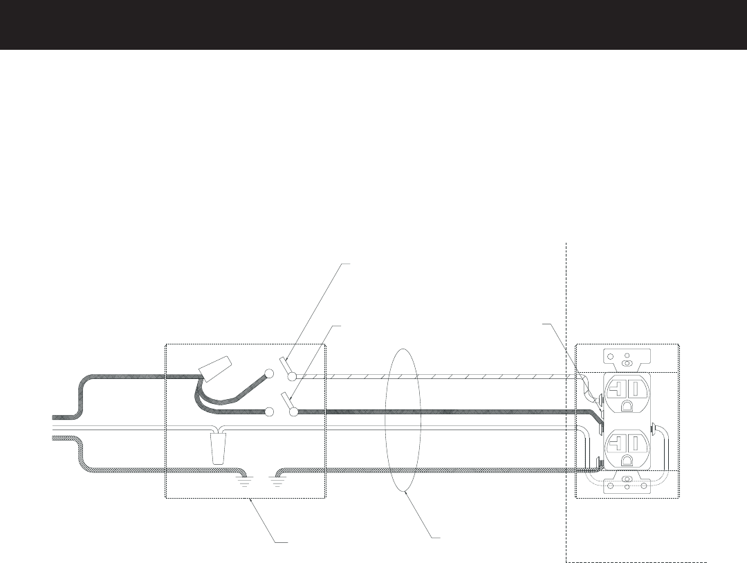
In order to install both the optional Blower and Accent Light ac-
cessories, it will be necessary to install the junction box so that
the Duplex Receptacle wiring is split. This will allow each side of
the receptacle to operate independently off separate wall switches.
See diagram below.
CAUTION: ALL WIRING SHOULD BE DONE BY A QUAL-
IFIED ELECTRICIAN AND SHALL BE IN COMPLIANCE
WITH ALL LOCAL, CITY AND STATE BUILDING CODES.
-
NECTED. THE APPLIANCE, WHEN INSTALLED, MUST
BE ELECTRICALLY GROUNDED IN ACCORDANCE
WITH LOCAL CODES OR, IN THE ABSENCE OF LOCAL
CODES, WITH THE NATIONAL ELECTRICAL CODE
#1
ACCENT LIGHT
WALL SWITCH
#2
BLOWER
WALL
SWITCH
REMOVE TABON HOT SIDE
OF DUPLEX RECEPTACLE
TO SPLIT LUGS
PLUG
FOR
CONTROLS
PLUG
FOR
BLOWER
FIREPLACE
CONTROL
COMPARTMENT
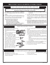
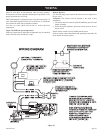
DUAL SWITCH ELECTRICAL WIRING TO FIREPLACE RECEPTACLE
RED
BLACK
WHITE
3-WIRE, GROUNDED
CONDUCTOR
(BY OTHERS)
DOUBLE SWITCH BOX
(INSTALLER PROVIDED)
BLACK
WHITE
GROUND
TO 120V
CIRCUIT
BREAKER
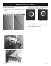
1. To wire Junction Box Receptacle, remove the tab on the side
of the receptacle (hot side) to split receptacle. This will be
required to separate blower and Accent Light circuits.
2. Power for switched and live sides of Duplex Receptacle must
come from the same power source. (One circuit breaker on
main panel must switch all power off.)
3. From the wall box to the replace a 3-wire conductor with
ground is recommended, however (2) two-wire conductors
with grounds may be used in place of a 3-wire conductor with
a ground if the black wires from the Accent Light and blower
accessories are identied.
4. Two wall switches may be used to activate the two receptacle
plugs independently.
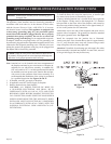
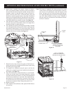
Note: Wiring to the Junction Box should be run through the 7/8"
diameter access hole located on one of the sides of the replace
outer wall. A Romex type connector is provided and should be
used to protect and restrain the wiring where it passes through
the replace outer wall. The Junction Box should be positioned in
the lower compartment of the replace/rebox so that it does not
interfere with moving parts of the blower assembly. The Junction
Box incorporates magnets on the bottom side to retain and reduce
the chance of movement or vibration during blower operation.
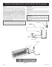
Note: If only the blower option is to be installed, wiring may be
performed as described and illustrated in the following Blower
Installation section.