


26670-0-0110Page 26
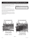
Attention: Install blower assembly before connecting gas in-
let supply line.
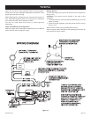
Wiring
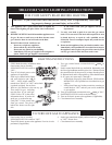
The appliance, when installed, must be electrically grounded in
accordance with local codes or, in the absence of local codes,
with the National Electrical Code, ANSI/NFPA 70, if an exter-
nal electrical source is utilized. This appliance is equipped with
a three-prong [grounding] plug for your protection against
shock hazard and should be plugged directly into a properly
grounded three-prong receptacle. Do not cut or remove the
grounding prong from this plug. For an ungrounded receptacle,
an adapter, which has two prongs and a wire for grounding, can
be purchased, plugged into the ungrounded receptacle and its wire
connected to the receptacle mounting screw. With this wire com-
pleting the ground, the appliance cord plug can be plugged into
the adapter and be electrically grounded.
Caution: Label all wires prior to disconnection when servic-
ing controls. Wiring errors can cause improper and dangerous
operation. Verify proper operation after servicing.
Note: Junction box is to be located in the lower compartment of
the replace and must be pre-wired at time of replace in-
stallation for use with blower assembly. A standard ON/
OFF wall switch or SCV-1 variable speed control kit should
be installed to activate power to the Junction Box and pro-
vide power for the operation of the blower assembly. It is
recommended that installation of the wiring be performed
by a qualied electrician.
1. If installed, turn OFF gas supply to replace.
2. If applicable, turn OFF electric supply to replace.
3. Remove bottom louver from replace.
CAUTION: ALL WIRING SHOULD BE DONE BY
A QUALIFIED ELECTRICIAN AND SHALL BE IN
COMPLIANCE WITH ALL LOCAL, CITY AND STATE
BUILDING CODES. BEFORE MAKING THE ELECTRI-
CAL CONNECTION, MAKE SURE THAT MAIN POWER
SUPPLY IS DISCONNECTED. THE APPLIANCE, WHEN
INSTALLED, MUST BE ELECTRICALLY GROUNDED
IN ACCORDANCE WITH LOCAL CODES, WITH THE
NATIONAL ELECTRICAL CODE ANSI/NFPA 70 (LAT-
EST EDITION).
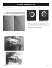
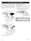
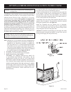
To install the blower kit, access the junction box, or install a light
kit, remove lower louver as illustrated by gure 21.
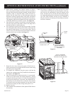
A factory included junction box is located on the lower right side
of the replace. Wiring must be fed through the 7/8" diameter
hole provided on the lower side of the replace, and secured to
the outer wrap with the clamp provided. Leave approximately 6”
of wire in the junction box for connection.
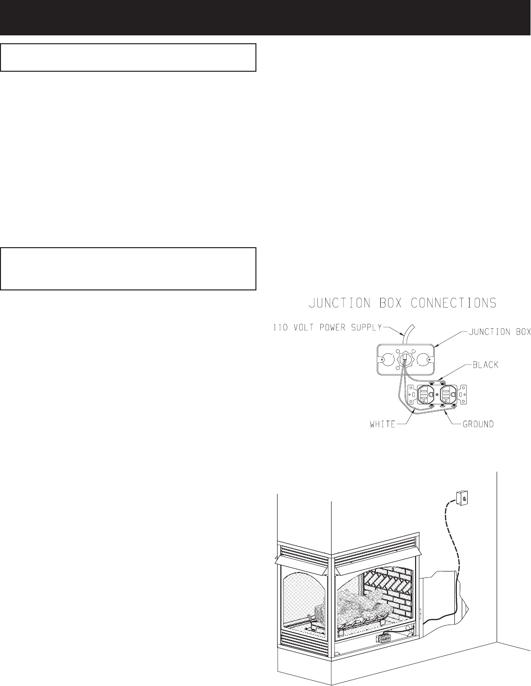
Attach black wire to one side of the receptacle and white wire to
opposite side of receptacle. The ground wire should be attached
to the green (ground) screw.
Install the receptacle into the junction box as illustrated.
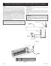
Attach cover plate. Place Junction Box so that it is approximately
8 to 12" away from the outer wrap wall. Secure wiring at outer
wrap of replace with wire clamp provided.
Attention: If installed, do not damage gas inlet supply line when
blower assembly is inserted into replace. In some cases, removal
of the gas inlet supply line may be necessary.