


26670-0-0110Page 10
Check all local codes for requirements, especially for the size and
type of gas supply line required.
Note: Never use plastic pipe. Check to conrm whether your local
codes allow copper tubing or galvanized.
Note: Since some municipalities have additional local codes, it is
always best to consult your local authority and installation code.
Installing a New Main Gas Cock
Each appliance should have its own manual gas cock.
A manual main gas cock should be located in the vicinity of
the unit. Where none exists, or where its size or location is not
adequate, contact your local authorized installer for installation
or relocation.
Compounds used on threaded joints of gas piping shall be resistant
to the action of liqueed petroleum gases. The gas lines must be
checked for leaks by the installer. This should be done with a soap
solution watching for bubbles on all exposed connections, and if
unexposed, a pressure test should be made.
be disconnected from piping at inlet of control valve and pipe
capped or plugged for pressure test. Never pressure test with
A gas valve and ground joint union should be installed in the gas
line upstream of the gas control to aid in servicing. It is required
by the National Fuel Gas Code that a drip line be installed near
the gas inlet. This should consist of a vertical length of pipe tee
connected into the gas line that is capped on the bottom in which
condensation and foreign particles may collect.
The use of the following gas connectors is recommended:
— ANS Z21.24 Appliance Connectors of Corrugated Metal Tubing
and Fittings
— ANS Z21.45 Assembled Flexible Appliance Connectors of
Other Than All-Metal Construction
The above connectors may be used if acceptable by the authority
having jurisdiction The state of Massachusetts requires that a exible
appliance connector cannot exceed three feet in length.
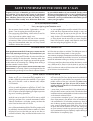
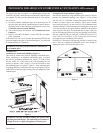
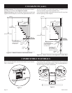
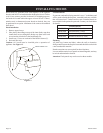
Figure 3
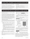
Checking Manifold Pressure
will have a manifold pressure
of approximately 3.5" w.c. (.871kPa) for maximum input or
1.7" w.c. (.423kPa) for minimum input at the pressure regulator outlet
with the inlet pressure to the pressure regulator from a minimum
of 4.5" w.c. (1.120kPa) for the purpose of input adjustment to a
maximum of 10.5" w.c. (2.614kPa).
will have a manifold pressure
approximately 10.0"w.c. (2.49kPa) at the pressure regulator outlet
with the inlet pressure to the pressure regulator from a minimum
of 11.0"w.c. (2.739kPa) for the purpose of input adjustment to a
maximum of 13.0"w.c. (3.237kPa).
A test gage connection is located downstream of the gas appliance
pressure regulator for measuring gas pressure. The connection is a
1/8 inch (3mm) N.P.T. plugged tapping.
MILLIVOLT CONTROL
The valve regulator controls the burner pressure which should be
checked at the pressure test point. Turn captured screw counter
clockwise 2 or 3 turns and then place tubing to pressure gauge over
test point (Use test point “A” closest to control knob). After taking
pressure reading, be sure and turn captured screw clockwise rmly
to re-seal. Do not over torque. Check for gas leaks.
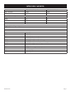
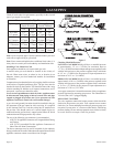
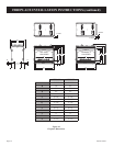
GAS SUPPLY
Recommended Gas Pipe Diameter
Pipe Length Schedule 40 Pipe
Inside Diameter
Tubing, Type L
Outside Diameter
Nat. L.P. Nat. L.P.
0-10 feet
0-3 meters
1/2”
12.7mm
3/8”
9.5mm
1/2”
12.7mm
3/8”
9.5mm
10-40 feet
4-12 meters
1/2”
12.7mm
1/2”
12.7mm
5/8”
15.9mm
1/2”
12.7mm
40-100 feet
13-30 meters
1/2”
12.7mm
1/2”
12.7mm
3/4”
19mm
1/2”
12.7mm
100-150 feet
31-46 meters
3/4”
19mm
1/2”
12.7mm
7/8”
22.2mm
3/4”
19mm