


21759-6-0608Page 24
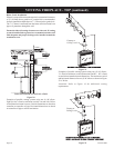
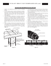
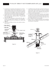
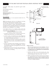
17. To attach the vent connections at the fireplace, be sure the 7”
diameter adapter collar has been installed per step 3. Apply
a bead of silicone sealant to the 4” diameter flex connector,
then slide the flex pipe adapter collar into the fireplace flue
collar and secure by installing a minimum of two (2) screws
through the flue collar and into the adapter. See Figure 36.
18. Apply sealant to the 7” diameter adapter collar, slide outer
flex vent over the collar, then secure with a 7” diameter band
clamp. See Figure 36.
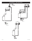
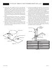
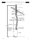
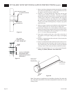
19. Once the lower connections are made and the flex pipe is
secured with support bands as required (3 feet minimum be-
tween supports) then the roof flashing can be installed. See
Figure 37.
20. Install the roof flashing, and seal using common construc-
tions practices.
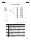
21. An additional storm collar band is provided in kit that may be
used as an attic insulation shield. The collar can be installed
around the flex pipe (or hard pipe) just above the firestop
thimble. This collar will act as a shield to prevent blown in-
sulation from entering the thimble.
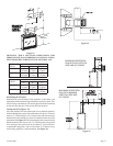
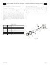
22. To complete the vent installation, install the vent termination
cap to the top of the hard vent pipe assembly. Mate up the flue
and outer telescopes with the hard pipe assembly, then secure
by installing a minimum of two (2) sheet metal screws into
the overlapped flanges of the cap and pipe.
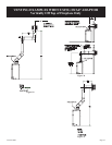
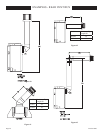
23. Figure 38 shows a completed installation with components
identified and other installation information such as heights
and clearance to combustibles.
BAND CLAMP
APPLY HIGH
TEMPERATURE
SEALANT
(WITH GASKET)
ADAPTER COLLAR
7" DIA. INLET
4" DIA. FLU
E
ADAPTER
COLLAR
FLUE PIP
E
4" DIA. FLEX
7” DIA. FLEX AIR
INTAKE PIPE
Vent Cap
Storm
Minimum
Clearance to
Combustibles
Collar
Exterior
Roof
Roof
Flashing
Support
Roof
Assembly
7"(178mm) Dia.
Must Extend
7"(178mm) Dia.
Hard Pipe
Through Roof
Flashing
1” (25mm)
Flex
Figure 36
Figure 37
DVVK-4FV DIRECT VENT TERMINATION KIT (cont.)